Electrically-powered programmable waste enclosure

a waste enclosure and programmable technology, applied in the direction of process and machine control, safety/protection circuits, emergency power supply arrangements, etc., to achieve the effect of efficient powering the electrical functions, generating advertising revenues, and offseting the cost of waste collection activities

a waste enclosure and programmable technology, applied in the direction of process and machine control, safety/protection circuits, emergency power supply arrangements, etc., to achieve the effect of efficient powering the electrical functions, generating advertising revenues, and offseting the cost of waste collection activities

US9352887B2Active Publication Date: 2016-05-31BIG BELLY SOLAR

Image

  • Electrically-powered programmable waste enclosure
  • Electrically-powered programmable waste enclosure
  • Electrically-powered programmable waste enclosure

Examples


Embodiment Construction

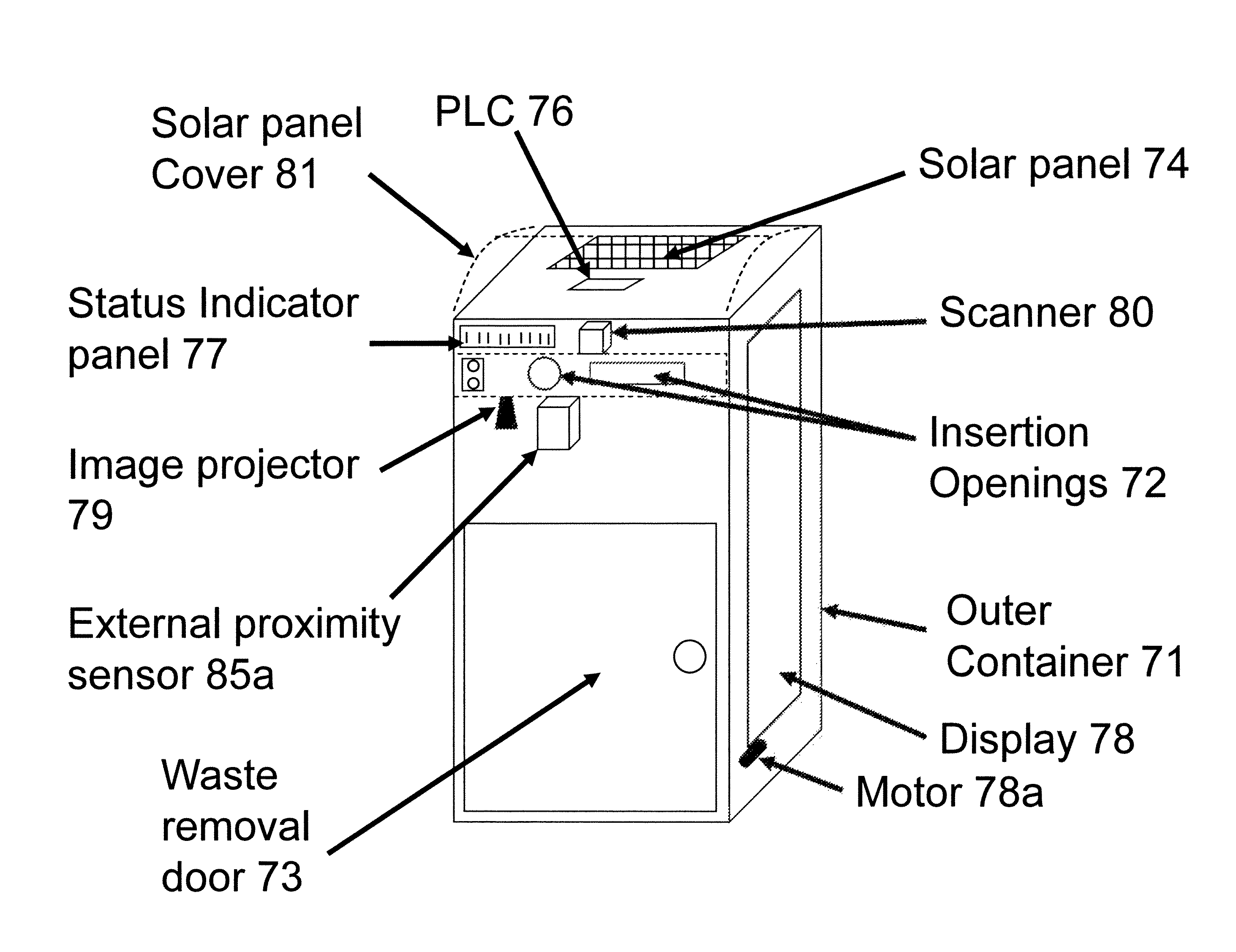
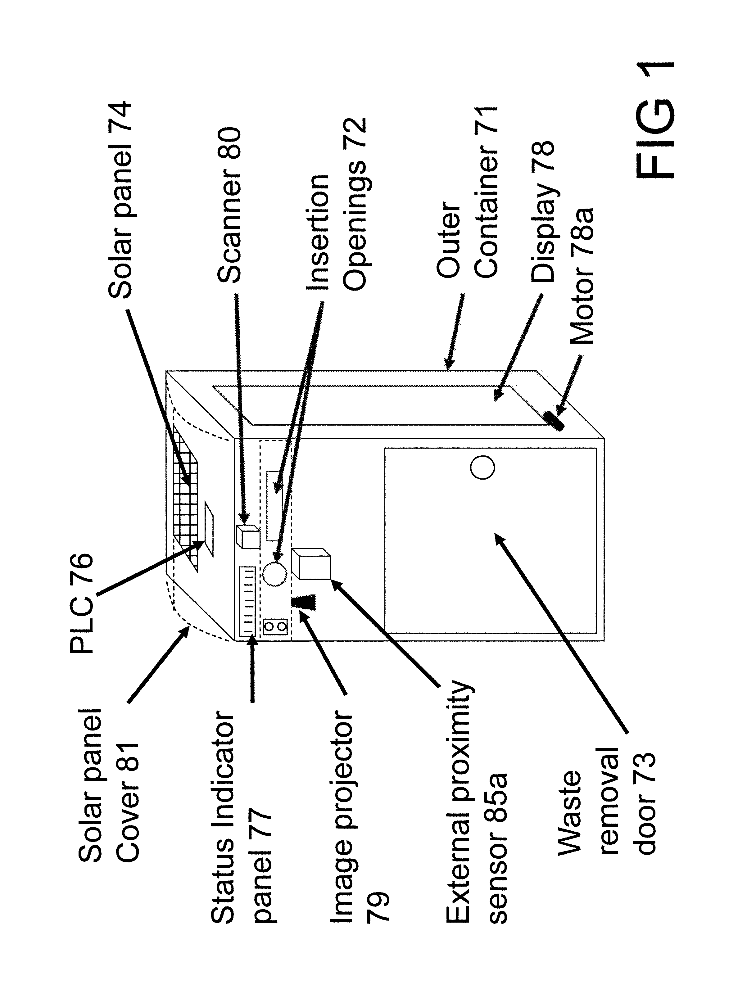
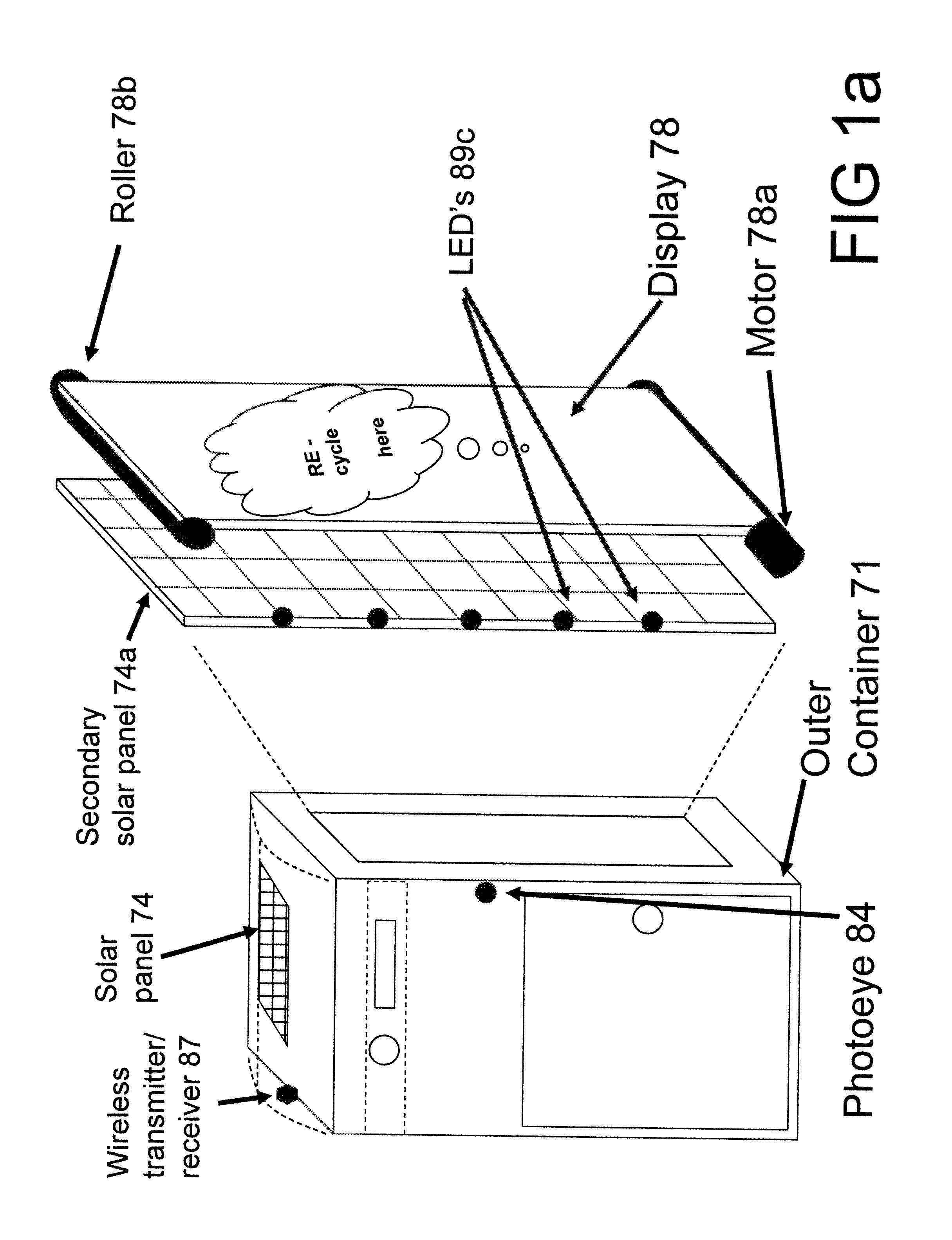
[0053]The present invention discloses a system of waste deposit and collection in an enclosure including integrated battery storage and solar energy generation mechanism and a method for employing such. Further disclosed are embodiments wherein an integrated battery storage and solar energy generation mechanism and monitoring / communicating capability are provided to incorporate into existing conventional trash containers or other containers and dumpsters.

[0054]This invention will be better understood with reference to the following definitions.

[0055]A. Ancillary electrical components shall be broadly construed to include electrical devices associated with or forming part of the waste enclosure device of this invention exclusive of the PLC and the battery. Ancillary electrical components include a photovoltaic panel, sensors such as those useful to determine waste deposits characteristics and contents, components adapted to send and receive data, optionally wirelessly; other electric...


PUM


Abstract

This invention is directed towards a waste enclosure device (ā€œdeviceā€) comprising a waste enclosure employing operational functions including collection and monitoring capacity wherein said device includes one or more programmable logic controllers. Operational functions are performed by electrical components including sensors to determine waste deposits characteristics and contents. Said device operational functions are further adapted to send and receive data, optionally wirelessly, and configured and adapted to utilize solar derived electric power and, optionally, electric power from other sources.

Description

RELATED APPLICATIONS[0001]This application is a national stage application of PCT / US2011 / 044855, filed Jul. 21, 2011 which claims the benefit of priority under 35 U.S.C. §119(e) to U.S. Provisional Application Ser. No. 61 / 368,392, filed Jul. 28, 2010, the disclosures of which are incorporated herein in their entirety by reference.FIELD OF THE INVENTION[0002]This invention is directed towards a waste enclosure device (ā€œdeviceā€) comprising a waste enclosure employing operational functions including collection and monitoring capacity wherein said device includes one or more programmable logic controllers. Operational functions are activities performed by electrical components including sensors to determine waste deposits characteristics and contents. These operational functions are further adapted to send and receive data, optionally wirelessly, and configured and adapted to utilize solar derived electric power and, optionally, electric power from other sources.BACKGROUND OF THE INVENT...

Claims


Application Information

Patent Timeline
31 May 2016
Publication
US9352887B2
IPC
B65D55/00; H02J9/00; B65F1/14; B65F1/00; G05B11/00
CPC
B65D55/00; B65F1/0033; B65F1/1426; B65F1/1468; H02J9/00; B65F2210/108; B65F2210/1121; B65F2210/128
Inventors
POSS, JAMES ANDREW; SATWICZ, JEFFREY T.