In-situ load system for calibrating and validating aerodynamic properties of scaled aircraft in ground-based aerospace testing applications

a technology for aerodynamic properties and aircraft, applied in the field of in-situ load systems for calibrating and validating aerodynamic properties of scaled aircraft, can solve the problems of difficult set-up, in-situ performance of balances cannot be fully integrated in the wtms, and prohibited robust system-level, so as to achieve the effect of minimizing measurement uncertainties

Active Publication Date: 2016-05-31
NASA
View PDF6 Cites 17 Cited by
  • Summary
  • Abstract
  • Description
  • Claims
  • Application Information

AI Technical Summary

Benefits of technology

[0012]One aspect of the present invention is an In-Situ Load System (ILS) that addresses the issues noted above. The ILS includes both physical hardware and a methodology that standardizes the check-loading process. The system-level capabilities minimize measurement uncertainties in the data collected during a wind-tunnel test. Furthermore, the ILS of the present invention is compact and simple. The ILS may be utilized in connection with internal balances or external semi-span type balances.

Problems solved by technology

As the primary source for aerodynamic force and moment data, balance calibrations play a critical role in the quality of the data collected during a wind-tunnel test; yet, the performance of a balance cannot be characterized in-situ while fully integrated in the WTMS.
Furthermore, since there are few recommendations available, the process of check-loading may vary from wind tunnel to wind tunnel.
This variability between facilities in combination with limited resources, such as traceable standards and required hardware, previously prohibited a robust system-level, in-situ characterization or validation of the WTMS.
More complex loadings are difficult to set-up and execute in a wind tunnel and may introduce more uncertainty than they quantify.
Axial force check-loads may be difficult to apply because applying these loads requires a pulley and cable setup.
This type of setup increases the odds that additional uncertainties will be introduced.
However, these loads cannot be applied consistently and confidently utilizing conventional methods.

Method used


Image

  • In-situ load system for calibrating and validating aerodynamic properties of scaled aircraft in ground-based aerospace testing applications
  • In-situ load system for calibrating and validating aerodynamic properties of scaled aircraft in ground-based aerospace testing applications
  • In-situ load system for calibrating and validating aerodynamic properties of scaled aircraft in ground-based aerospace testing applications

Examples


Embodiment Construction

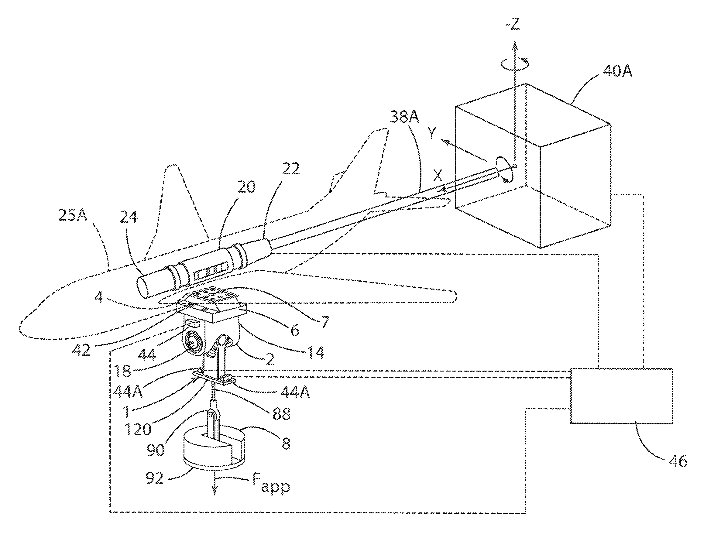
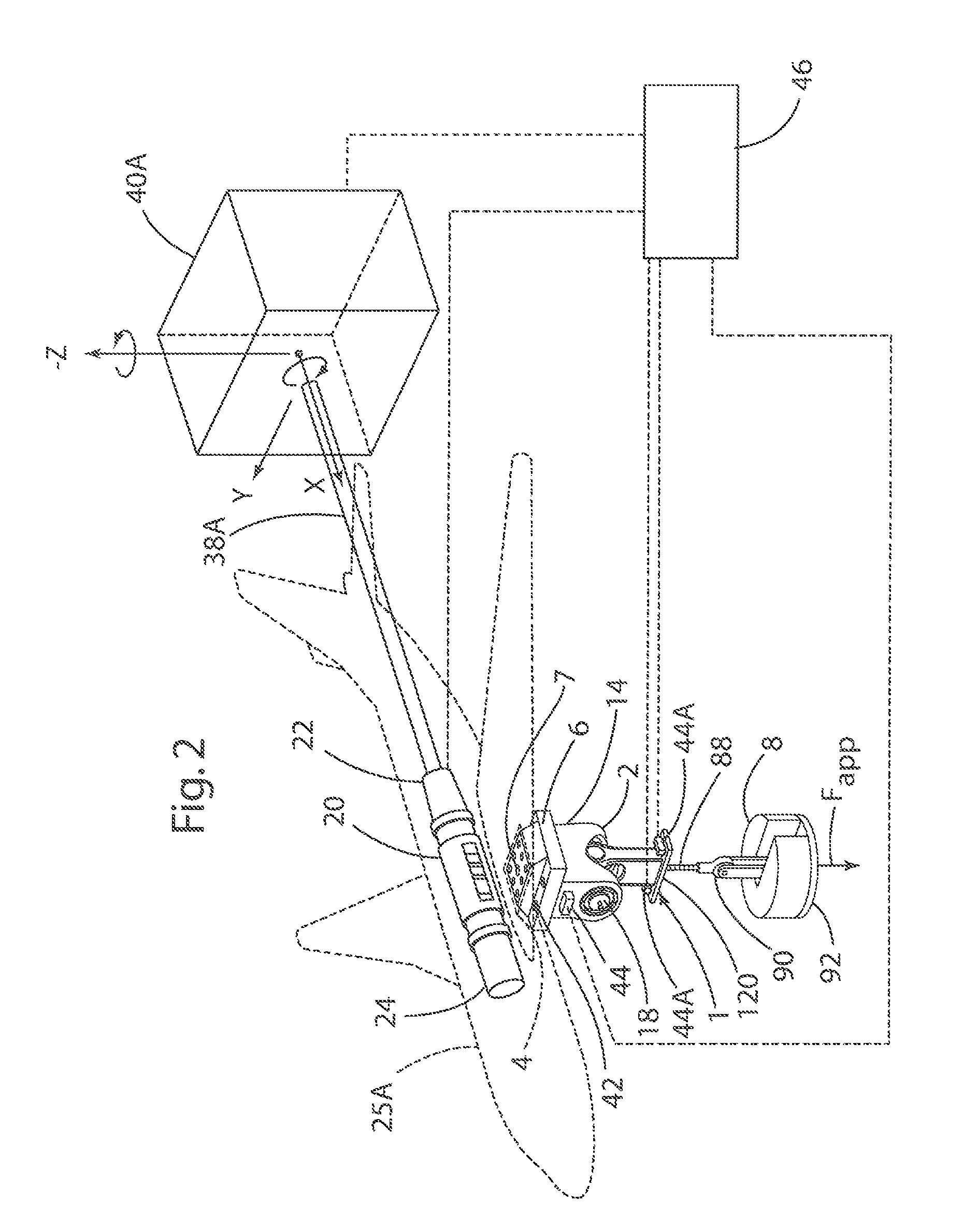
[0025]For purposes of description herein, the terms “upper,”“lower,”“right,”“left,”“rear,”“front,”“vertical,”“horizontal,” and derivatives thereof shall relate to the invention as oriented in FIG. 2. However, it is to be understood that the invention may assume various alternative orientations and step sequences, except where expressly specified to the contrary. It is also to be understood that the specific devices and processes illustrated in the attached drawings, and described in the following specification, are simply exemplary embodiments of the inventive concepts defined in the appended claims. Hence, specific dimensions and other physical characteristics relating to the embodiments disclosed herein are not to be considered as limiting, unless the claims expressly state otherwise.

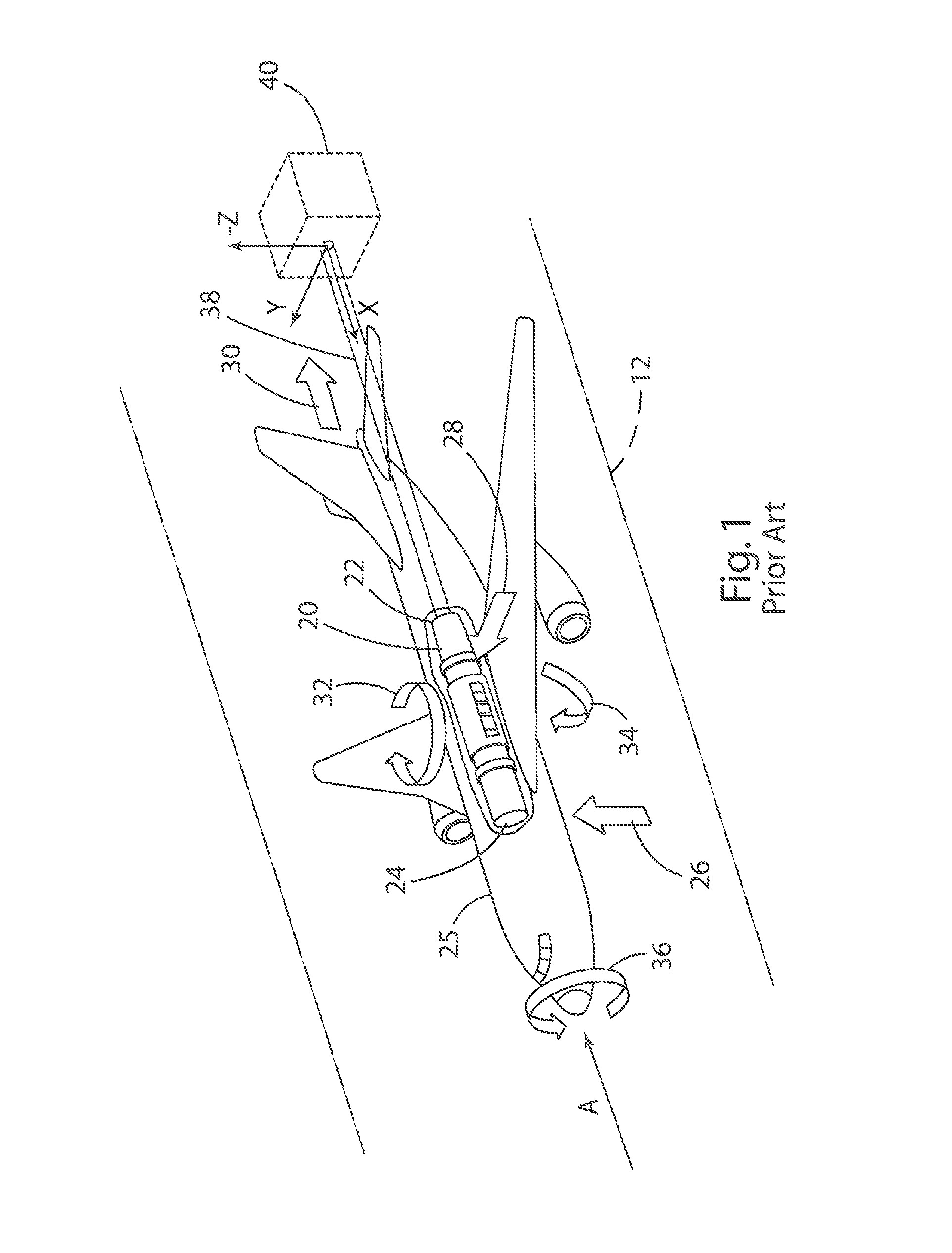
[0026]Referring again to FIG. 1, in a typical known wind tunnel test, wind tunnel aerodynamic loads acting on model 25 include a normal (lift) force 26, a side force 28, and an axial (drag) force 30. ...


PUM

PropertyMeasurementUnit
lengthaaaaaaaaaa
lengthaaaaaaaaaa
degrees of freedomaaaaaaaaaa

Abstract

An In-Situ Load System for calibrating and validating aerodynamic properties of scaled aircraft in ground-based aerospace testing applications includes an assembly having upper and lower components that are pivotably interconnected. A test weight can be connected to the lower component to apply a known force to a force balance. The orientation of the force balance can be varied, and the measured forces from the force balance can be compared to applied loads at various orientations to thereby develop calibration factors.

Description

CROSS-REFERENCE TO RELATED APPLICATION[0001]This application claims the benefit of U.S. Provisional Application No. 61 / 774,873 titled “IN-SITU LOAD SYSTEM FOR CALIBRATING AND VALIDATING AERODYNAMIC PROPERTIES OF SCALED AIRCRAFT IN GROUND-BASED AEROPACE TESTING APPLICATIONS” filed on Mar. 8, 2013, the entire contents of which are incorporated by reference.STATEMENT REGARDING FEDERALLY SPONSORED RESEARCH OR DEVELOPMENT[0002]The invention described herein was made in part by employees of the United States Government and may be manufactured and used by or for the Government of the United States of America for governmental purposes without the payment of any royalties thereon or therefore.BACKGROUND OF THE INVENTION[0003]Wind-tunnel balances are multi-dimensional force transducers used to obtain high-precision measurements of the aerodynamic loads on an aircraft model during wind-tunnel testing. In many wind tunnels, these aerodynamic measurements are made with the measurement device ins...

Claims


Application Information

Patent Timeline
Patent Type & Authority Patents(United States)
IPC IPC(8): G01L25/00
CPCG01L25/00G01M9/062
Inventor COMMO, SEAN A.LYNN, KEITH C.LANDMAN, DREWACHESON, MICHAEL J.
Owner NASA
Why Eureka
Try Eureka