Intermediate electrical connector and electrical connector assembled component

a technology of electrical connectors and components, applied in the direction of coupling devices, two-part coupling devices, electrical apparatus, etc., can solve the problems of difficult shielding sections, difficult to stably transmit signals, and noise at the contact parts, so as to improve the grounding effect, and facilitate the effect of maintaining the precision of physical relationships

Active Publication Date: 2016-05-31
HIROSE ELECTRIC GROUP
View PDF2 Cites 10 Cited by
  • Summary
  • Abstract
  • Description
  • Claims
  • Application Information

AI Technical Summary

Benefits of technology

[0021]According to the conventional intermediate electrical connector described above, the mating contact portions formed on the mating terminals are shielded by the mating ground plate from the opposite side to the contact surfaces of the mating contact portions. On the other hand, according to the first aspect of the present invention, in a state that the connectors are fitted, the contact parts where the contact portions and the mating contact portions contact each other are shielded by the second ground plate and the mating ground plate from both sides in the plate thickness direction of the blade. As a result, in the contact parts, it is possible to transmit signals without influence from noises from outside.
[0035]Therefore, it is possible to securely protect the contact parts from influence of noises from outside. Moreover, the second ground plates and the ground terminals are separate members. As for the second ground plates, it is possible to freely design the parts that correspond to the signal contact portions of the signal terminals. Therefore, forming the second ground plates in a shape so as to be able to match impedance at the contacting parts between the signal terminals, it is possible to easily adjust the impedance. As a result, it is achievable to stably transmit signals.

Problems solved by technology

Therefore, there is concern that signal transmission at the contact parts could be affected by noises from outside.
Therefore, it is not easy to provide a shielding section that enables to obtain preferred impedance.
For this reason, according to Patent Reference, it is difficult to stably transmit signals.

Method used


Image

  • Intermediate electrical connector and electrical connector assembled component
  • Intermediate electrical connector and electrical connector assembled component
  • Intermediate electrical connector and electrical connector assembled component

Examples


Embodiment Construction

[0052]Hereunder, embodiments of the present invention will be described with reference to the accompanying drawings.

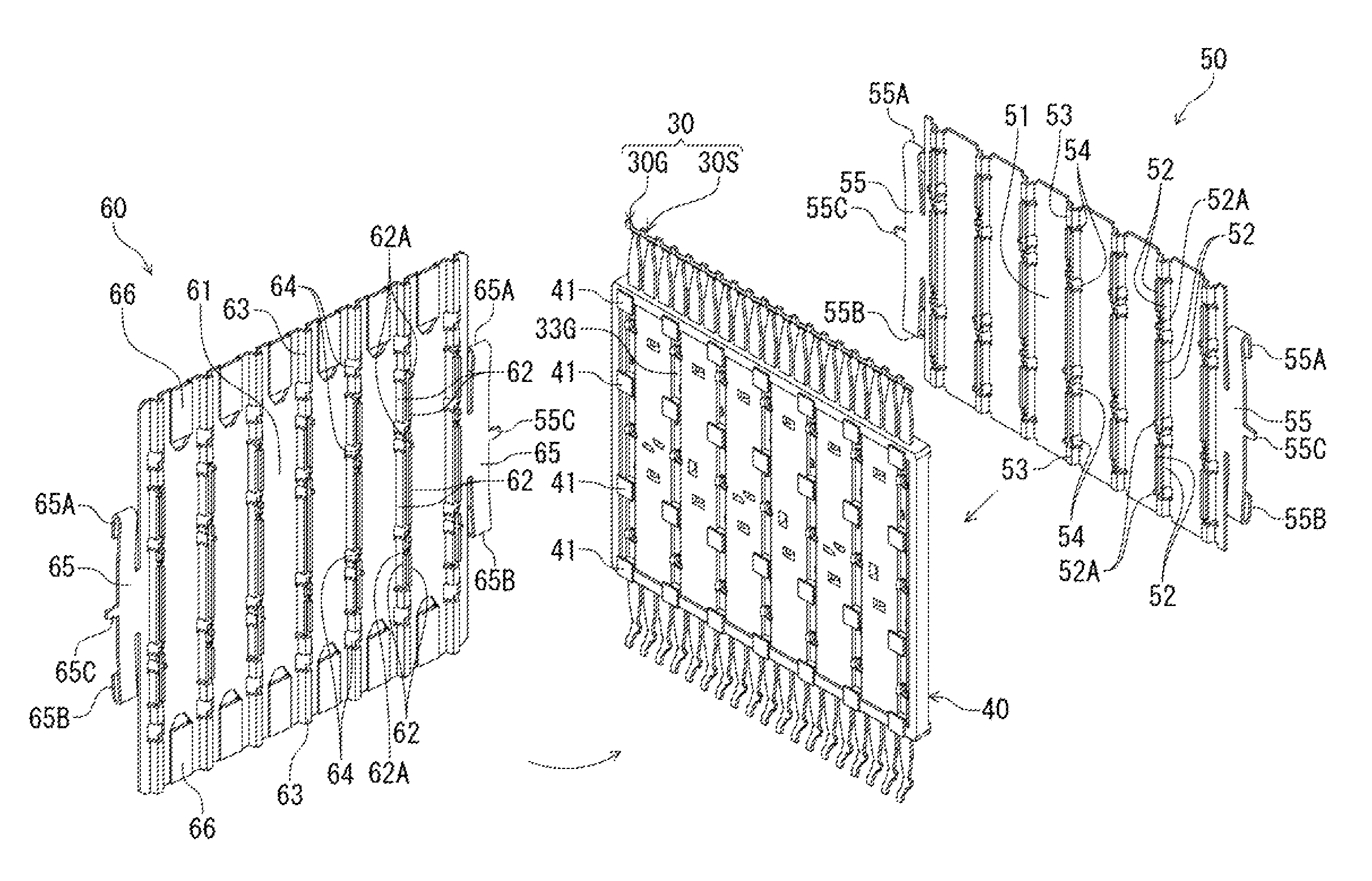
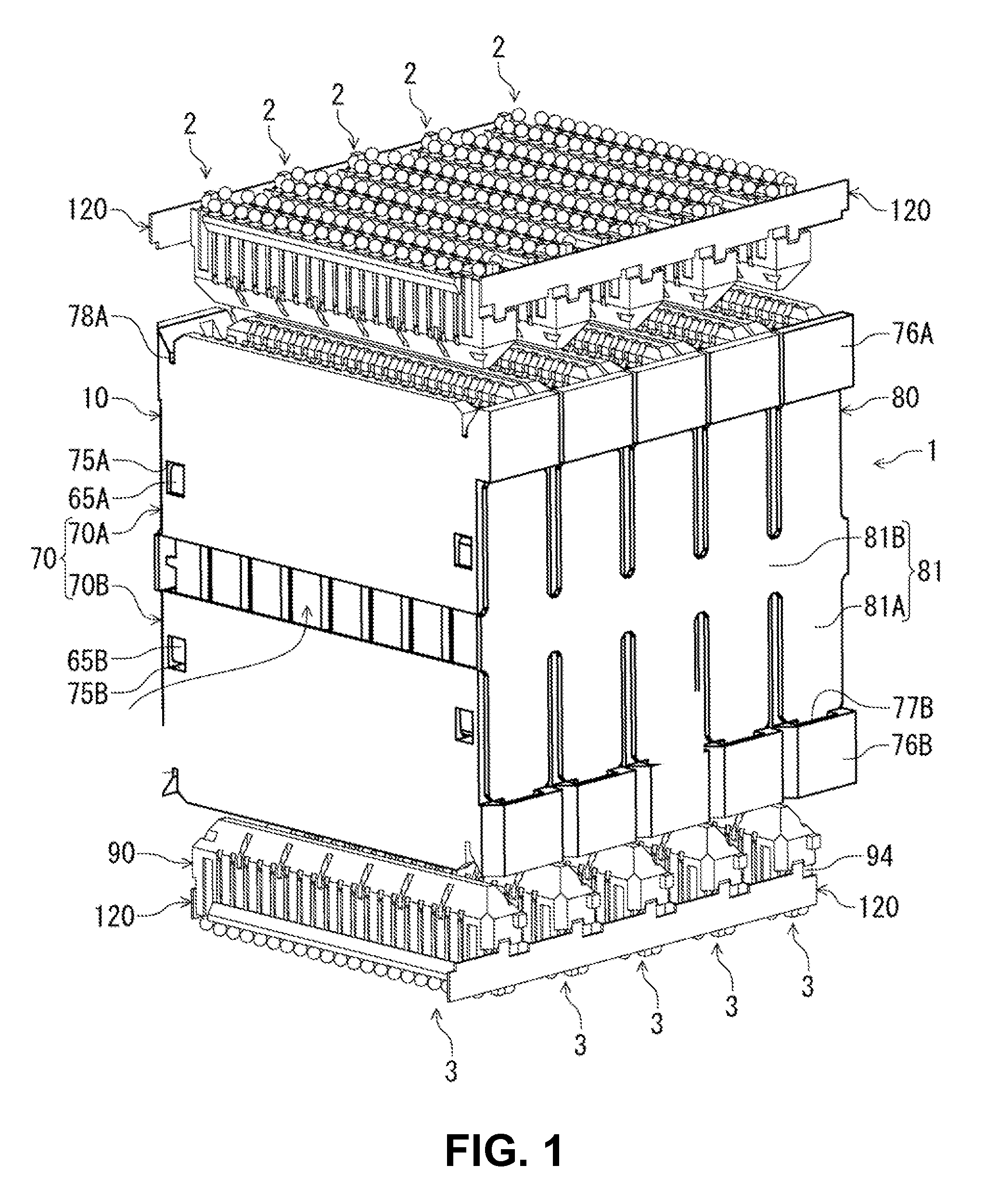
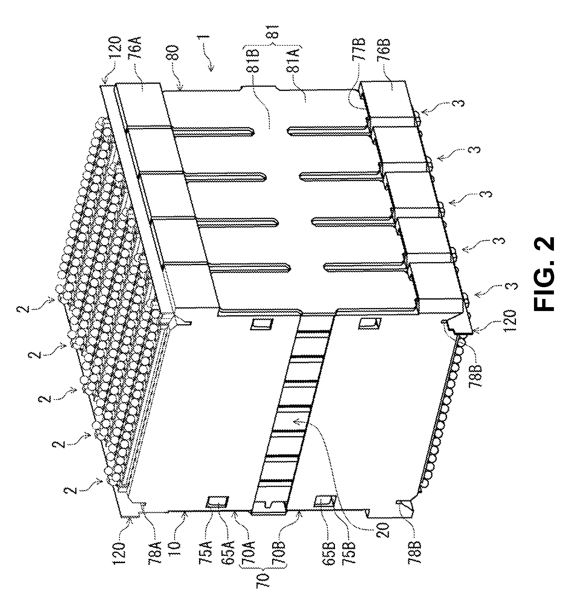
[0053]FIG. 1 is a perspective view showing an intermediate electrical connector according to the embodiment of the invention, which shows with mating connectors thereof, in a state before fitting to the intermediate electrical connector. FIG. 2 is a perspective view showing the intermediate electrical connector of FIG. 1 and the mating connectors thereof in their fitted states.

[0054]As shown in FIG. 1, to the intermediate electrical connector 1 of the embodiment (hereinafter simply referred to as “relay connector 1”), connected are mating connecting bodies, mating connectors 2 and 3, from thereabove and thereunder, respectively. The intermediate electrical connector relays and connects between the mating connectors 2 and 3. The mating connectors 2 and 3 are electrical connectors to be used on circuit boards, have the same shapes, and are to be connected to circuit boar...


PUM


Abstract

An intermediate electrical connector to be connected to a mating connecting member includes an intermediate connecting member; and a blade disposed in the intermediate connecting member. The blade includes a first ground plate, a second ground plate, a base member, a signal terminal, and a ground terminal. The signal terminal includes a first contact portion and a first connecting portion connected to the first contact portion. The ground terminal includes a second contact portion and a second connecting portion connected to the second contact portion. The first ground plate is situated on one side of the blade over the first connecting portion and the second connecting portion. The second ground plate is situated on an opposite side of the blade over the first connecting portion, the second connecting portion, the first contact portion, and the second contact portion.

Description

BACKGROUND OF THE INVENTION AND RELATED ART STATEMENT[0001]The present invention relates to an intermediate electrical connector for connecting to a mating connecting member, which may include a mating connector or a circuit board. The present invention also relates to an electrical connector assembled component equipped with the intermediate electrical connector and the mating connector thereof.[0002]As a conventional connector and a conventional electrical connector assembled component of this type, for example, Patent Reference has disclosed a conventional intermediate electrical connector.Patent Reference: United States Patent Application Publication No. 2012 / 0214343[0003]According to Patent Reference, the conventional electrical connector assembled component is mounted on a circuit board that forms a horizontal surface, and is fitted and connected to a mating connector from a side of the conventional intermediate electrical connector. Here, the mating connector includes an elec...

Claims


Application Information

Patent Timeline
Patent Type & Authority Patents(United States)
IPC IPC(8): H01R24/00H01R12/70H01R13/6582H01R13/6586H01R13/518
CPCH01R12/7082H01R13/6582H01R13/6586H01R12/707H01R13/518
Inventor TAMAI, NOBUHIRO
Owner HIROSE ELECTRIC GROUP
Why Eureka
Try Eureka