Check patentability & draft patents in minutes with Patsnap Eureka AI!

End piece of wheel cylinder piston adjustor

a technology of adjusting piston and end piece, which is applied in the direction of lifting devices, braking elements, hoisting equipment, etc., can solve the problems of affecting the service life of the vehicle, so as to facilitate the service of the vehicle and move smoothly

Active Publication Date: 2016-06-28
YANG JEN YUNG
View PDF15 Cites 13 Cited by
  • Summary
  • Abstract
  • Description
  • Claims
  • Application Information

AI Technical Summary

Benefits of technology

This design enhances the reliability and longevity of the wheel cylinder piston adjustor by preventing wear and enabling seamless operation on different-sized pistons, facilitating easier maintenance and service.

Problems solved by technology

Therefore, the wear of the linings is inevitable.
In this case, after a period of use, the locating bolts 3 and the slide slots 6 are likely to wear due to relative sliding.
As a result, the locating bolts 3 are likely to clog and can be hardly smoothly slid.
Therefore, in practice, the conventional end piece 1 cannot be conveniently used and needs to be improved.

Method used


Image

  • End piece of wheel cylinder piston adjustor
  • End piece of wheel cylinder piston adjustor
  • End piece of wheel cylinder piston adjustor

Examples


Embodiment Construction

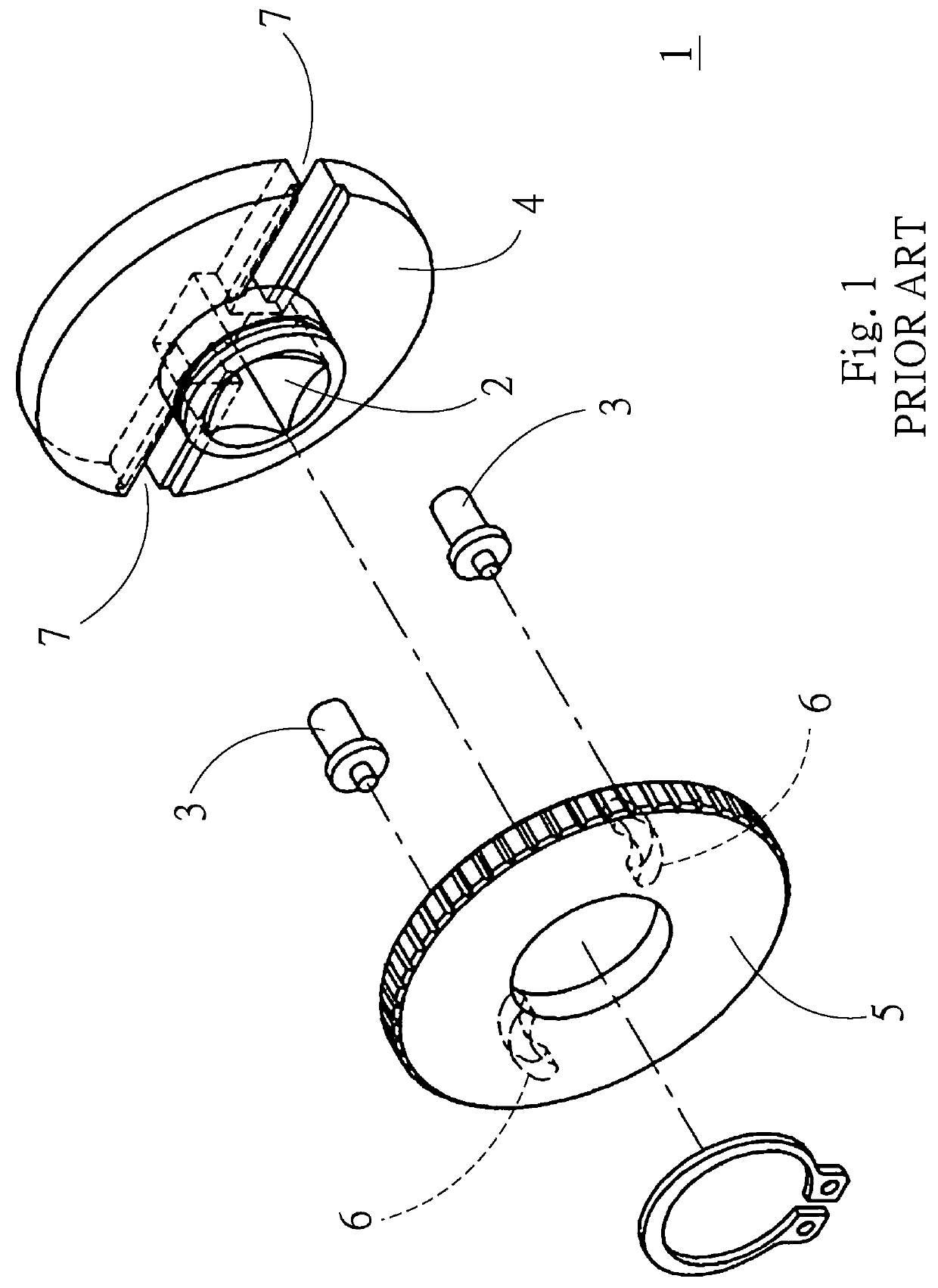
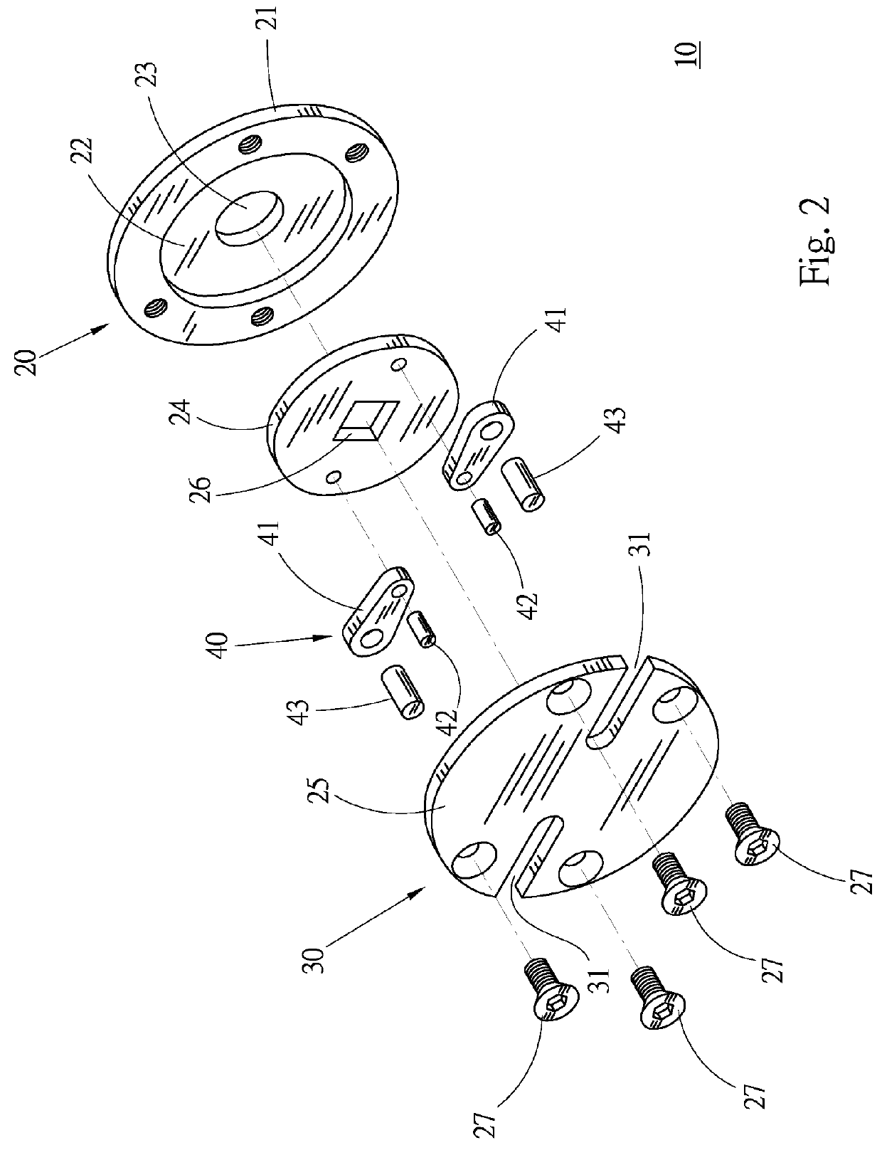
[0030]Please refer to FIGS. 2 to 6. According to a preferred embodiment, the end piece 10 of wheel cylinder piston adjustor of the present invention is a part of the conventional wheel cylinder piston adjustor. The end piece 10 abuts against the end of the wheel cylinder piston and is driven by the drive end of the wheel cylinder piston adjustor. Accordingly, the action force applied by the wheel cylinder piston adjustor can be transmitted by the end piece 10 to the wheel cylinder piston so as to push the wheel cylinder piston back into the piston room. Substantially, the end piece 10 includes a seat section 20, a guide section 30 and a locating section 40.

[0031]The seat section 20 has a plate-shaped seat body 21. A move space 22 in the form of a recess is formed on one face of the seat body 21. A shaft hole 23 is formed through a curvature center of the seat body 21 in communication with the move space 22. A rotary body 24 in the form of a circular plate is freely rotatable receive...


PUM


Abstract

An end piece of wheel cylinder piston adjustor includes a seat section and a rock arm. One end of the rock arm is pivotally connected with the seat section via a pivot pin, whereby the rock arm is rotatable around the pivot pin. A locating body is disposed at the other end of the rock arm and extends through a guide slot. When the rock arm is swung, the locating body is driven to synchronously move within the guide slot so as to change the distance between the locating bodies connected with the end of the wheel cylinder piston. The locating bodies can be smoothly moved to facilitate the vehicle service work.

Description

BACKGROUND OF THE INVENTION[0001]1. Field of the Invention[0002]The present invention relates generally to a vehicle service tool, and more particularly to an end piece of wheel cylinder piston adjustor.[0003]2. Description of the Related Art[0004]It is known that the disc brake of a vehicle includes two brake discs rotatable with the wheels. A brake calipers is used to clamp the brake discs so as to brake the wheel. The rotational speed of the brake discs is slowed down so as to slow down the vehicle or stop the vehicle. Substantially, the brake main cylinder provides fluid pressure through a pipeline to the wheel cylinder of the brake calipers. The piston of the wheel cylinder is axially moved to push the linings connected with the piston. At this time, the linings tightly abut against the faces of the brake discs to apply a frictional force against the move of the brake discs. Under such circumstance, the rotational speed of the wheel is reduced so as to slow down or stop the veh...

Claims


Application Information

Patent Timeline
Patent Type & Authority Patents(United States)
IPC IPC(8): B25B27/00B66F19/00F16D65/00
CPCB66F19/00F16D65/0043
Inventor YANG, JEN-YUNG
Owner YANG JEN YUNG
Features
  • R&D
  • Intellectual Property
  • Life Sciences
  • Materials
  • Tech Scout
  • Unparalleled Data Quality
  • Higher Quality Content
  • 60% Fewer Hallucinations
Learn More