End cap for a tubular light source

a technology for end caps and light sources, which is applied in the direction of light source semiconductor devices, coupling device connections, lighting and heating apparatus, etc. it can solve the problem of unintentional push by the installer of the safety mechanism, and achieve the effect of simplifying installation and higher safety level

Active Publication Date: 2016-06-28
KONINK PHILIPS ELECTRONICS NV
View PDF23 Cites 2 Cited by
  • Summary
  • Abstract
  • Description
  • Claims
  • Application Information

AI Technical Summary

Benefits of technology

[0008]The present invention is based on the realization that a safety switch for a tubular light source may advantageously be integrated into the end cap of the tube and that the safety switch preferably is automatically closing an electrical circuit by forming a conductive path between the socket and the tubular light source during installation of such a light source. In particular, in some tubular light sources, the internal circuitry is arranged so that the light source may provide a conductive path from the connector pins in one end portion of an elongate tube to connector pins in the opposite end portion even if the light source is not active contrary to what was possible in conventional fluorescent light tubes. In other words, it is possible that mounting one end portion of the tubular light source in the socket of the lighting fixture leads to the connector pins in the opposite end portion carrying a live voltage. In particular, having a push-in mechanism arranged on the end cap may cause the installer to unintentionally push the safety mechanism, thereby engaging the electrical circuit, during installation of the tubular light source. By having a switch which automatically closes an electrical circuit only when the connector pins are out of reach for the installer, the risk for the installer of receiving an electrical shock when installing a tubular light source is significantly reduced. A further advantage of the present invention is that a double safety feature is provided which is integrated in an end cap for a tubular light source. The double safety feature is provided through a switch assembly where the electrical circuit is closed only through a combination of a push-movement of the switch element and a rotational movement of either the end cap or the tubular light source. One way to mount a tube light in a fixture is to first push the pins into the socket, thereby simultaneously engaging the push part of the safety switch. Thereafter the tubular light source may be rotated, either as a part of the mounting procedure as is the case for some fixtures or as a separate second step operative to close the electrical circuit from one end portion of the tubular light source to the other. In the first case, the circuit is closed as a part of the mounting procedure and in the second case an additional rotational motion is required, either way provides a double safety feature requiring two steps to close the electrical circuit. An additional advantage is that the end cap according to the present invention is compatible with and thereby provides safety for a plurality of different sockets. As an example, the end cap may be used in fixtures equipped with either of G5 and G13 type lamp sockets.
[0009]According to one embodiment, the end cap may advantageously comprise a second housing portion rotationally movable in relation to the first housing portion, wherein the conductive path is formed through a rotation of the second housing portion in relation to the first housing portion when the switch element is depressed.
[0010]Additionally, the second housing portion may be at least partially arranged inside the first housing portion.
[0011]Furthermore, the end cap may comprise conductive receiving means arranged in the second housing portion and configured to receive the connector pins through a rotation of the second housing portion in relation to the first housing portion, and wherein the electrically conductive receiving means are configured to be axially aligned with the connector pins only when the switch element is depressed. Consequently, the connector pins may preferably extend into the second housing portion where the connection between the pins and the receiving means is made. The electrically conductive receiving means may advantageously be arranged on a plate which in turn is mechanically connected to the axially movable switch element. The axial alignment of the electrically conductive receiving means and the connector pins thereby enables the connection between the socket and the light source as the end cap is mounted. Thus, if the rotational movement is performed without the switch element being depressed, there would be no electrical contact between the connector pins and the light source as the electrically conductive receiving means would be positioned in another axial plane. Additionally, spring means may advantageously be connected to the plate or the switch element in order to return the switch element to an un-pressed position when no external pressure is applied. The spring means may be a coil spring connected to the plate, but it may equally well be any other elastic element arranged to return the switch element to an un-pressed position.
[0012]In one embodiment, the switch element at least partly arranged on the outside of the housing may advantageously be a peg protruding in between the two connector pins. Having a peg or any similar structure protruding between the connector pins provides a simple way to depress the peg as the end cap is installed into a fixture, thereby performing the first step in the two-step process of creating a conducting path. The peg is preferably designed and configured so as to ensure that it is depressed when mounted in the intended fixture. The switch element should furthermore be activated at a relatively high force in order to reach a higher safety level as it may be possible for the installer to apply some force on the switch element during installation, thereby accidentally depressing the switch element.
[0013]In one embodiment, the second housing portion may advantageously be connected to the first housing portion by spring means acting in a rotational direction, the spring means being configured to return the relative rotational position of the first and second housing portions to an idle position. The spring means are operative to return the relative rotational position of the inner and the first housing portion in the case where the switch element is not depressed. However, the force of the electrically conductive receiving means in the rotational direction is preferably larger than the aforementioned spring force between the inner and first housing portion in order to maintain a conductive path between connector pins and the electrically conductive receiving means after a rotation has been performed while the switch element was depressed. The spring means may be coil springs, leaf springs, elastic elements or any similar structure.

Problems solved by technology

In particular, having a push-in mechanism arranged on the end cap may cause the installer to unintentionally push the safety mechanism, thereby engaging the electrical circuit, during installation of the tubular light source.

Method used


Image

  • End cap for a tubular light source
  • End cap for a tubular light source
  • End cap for a tubular light source

Examples


Embodiment Construction

[0025]The present invention will now be described more fully hereinafter with reference to the accompanying drawings, in which currently preferred embodiments of the invention are shown. This invention may, however, be embodied in many different forms and should not be construed as limited to the embodiments set forth herein; rather, these embodiments are provided for thoroughness and completeness, and fully convey the scope of the invention to the skilled person. Like reference characters refer to like elements throughout.

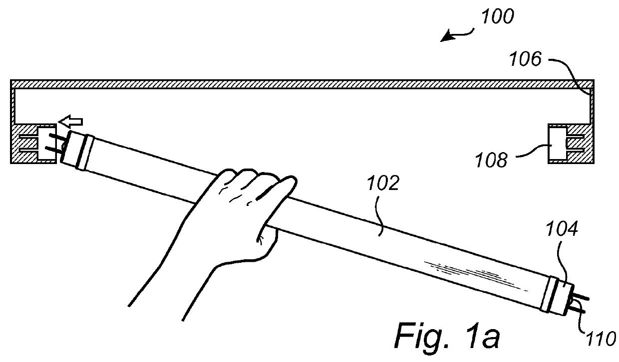
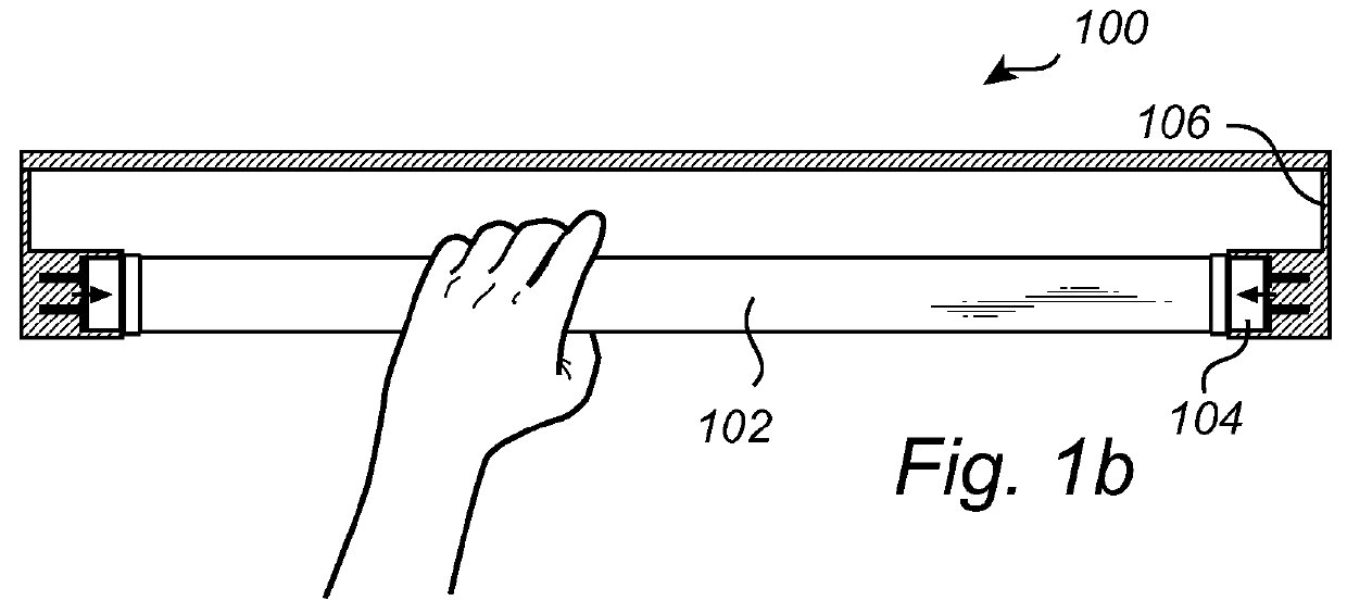
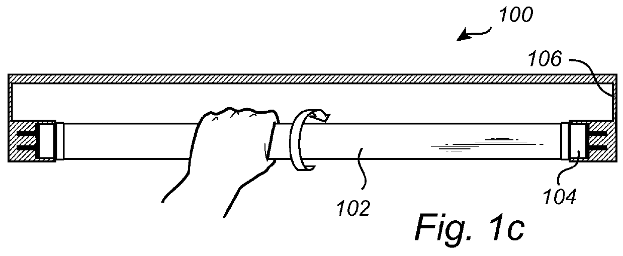
[0026]In the following, various embodiments of an end cap according to the present invention are mainly discussed with reference to an end cap for a tubular light source providing safety through a two-step mechanism including both an axial and a rotational motion. It should be noted that this by no means limits the scope of the present invention which is equally applicable to safety mechanisms for end caps where safety is provided by means of a first housing porti...


PUM


Abstract

An end cap (104) for a tubular light source (102), the tubular light source (102) configured to be arranged in a lighting fixture (106) comprising at least one socket (108), wherein the end cap (104) comprises, a first housing portion (202), two connector pins (208) at least partly arranged on an outside of the first housing portion (202) and adapted to fit in the socket (108), and a switch assembly comprising a switch element, wherein the switch assembly being adapted to form a conductive path between the socket (108) and the tubular light source (102) through a depression of the switch element in combination with a relative rotational motion of the first housing portion (202) in relation to the tubular light source (102) as the tubular light source (102) is mounted in the fixture (106).

Description

CROSS-REFERENCE TO PRIOR APPLICATIONS[0001]This application is the U.S. National Phase application under 35 U.S.C. §371 of International Application No. PCT / IB2012 / 051274, filed on Mar. 16, 2012, which claims the benefit of and priority to European Patent Application No. 11160372.6, filed on Mar. 30, 2011. These applications are hereby incorporated by reference herein.FIELD OF THE INVENTION[0002]The present invention relates to an end cap for a tubular light source, and in particular to an end cap enabling safe installation of such a tubular light source.BACKGROUND OF THE INVENTION[0003]Fluorescent lighting tubes are commonly used in a large range of lighting systems as a result of advantages such as longer life time and better luminous efficiency compared to incandescent lamps. However, in the continuous effort to reduce power consumption, it is desirable to replace conventional light tubes with still more energy efficient and environmental friendly alternatives. One such alternati...

Claims


Application Information

Patent Timeline
Patent Type & Authority Patents(United States)
IPC IPC(8): F21V25/00F21V19/00F21V23/04H01R13/71H01R33/96F21K99/00F21V25/02
CPCF21V25/00F21K9/175F21V19/008F21V23/04H01R13/71H01R33/96F21K9/17F21V25/02F21Y2101/02F21K9/272F21Y2115/10F21K9/27
Inventor VERHOEVEN, MARKGIELEN, VINCENT
Owner KONINK PHILIPS ELECTRONICS NV
Why Eureka
Try Eureka