Hand-held voltmeter for electric fence

a voltmeter and electric fence technology, applied in the field of voltmeters, can solve the problems of weak current flowing through the animal, electric fence experiencing unwanted low voltage on the fence wire, weak current flowing through the fence, etc., and achieves the effect of accurate measurement of the peak voltage of the electric fence, convenient use and quick measuremen

Active Publication Date: 2017-11-28
CHO BYUNG HAK
View PDF7 Cites 0 Cited by
  • Summary
  • Abstract
  • Description
  • Claims
  • Application Information

AI Technical Summary

Benefits of technology

[0014]The electric fence voltmeter 1 may have a sufficiently high measurement coupling factor enough to eliminate the need for connecting the ground of the voltmeter to the earth. The measurement coupling factor is defined as the ratio of the voltage detected from the voltmeter to the voltage applied to the electric fence.
[0015]More specifically, the measurement coupling factor may be increased by adequately arranging the various stray capacitances acting on the voltmeter.
[0017]According to the exemplary embodiments, the present disclosure provides a voltmeter that can measure the peak voltage of an electric fence accurately without need to make a ground connection to the earth, thereby having an advantage of becoming easy to use and allowing quick measurement.
[0018]In addition, the voltmeter has a low risk of an electric shock during the measurement.

Problems solved by technology

If an animal is in contact with the fence wire, a strong pain is caused by an electric shock due to the circulating current flowing through the animal.
Sometimes, the electric fence experiences unwanted low voltage on the fence wire due to the various reasons including the failure of the electric fence energizer itself, the fence wire in contact with trees or weeds, the broken or sagging fence wire on the ground, and the broken insulators.
Once the fence voltage is lowered, the current flowing through the animal becomes weak or may not flow at all.
However, this device has a problem with a poor measurement accuracy especially when the fence voltage is low.
In this reason, the measurement process of the conventional voltmeters is known to be too cumbersome, and takes long time to use.
In addition, since the high voltage probe of the conventional voltmeter is usually disposed close to the case, it may inadvertently cause an electric shock to a user during a measurement.

Method used


Image

  • Hand-held voltmeter for electric fence
  • Hand-held voltmeter for electric fence
  • Hand-held voltmeter for electric fence

Examples


first embodiment

[0052]Now, the present disclosure which reflects the aforementioned design considerations will be described in detail.

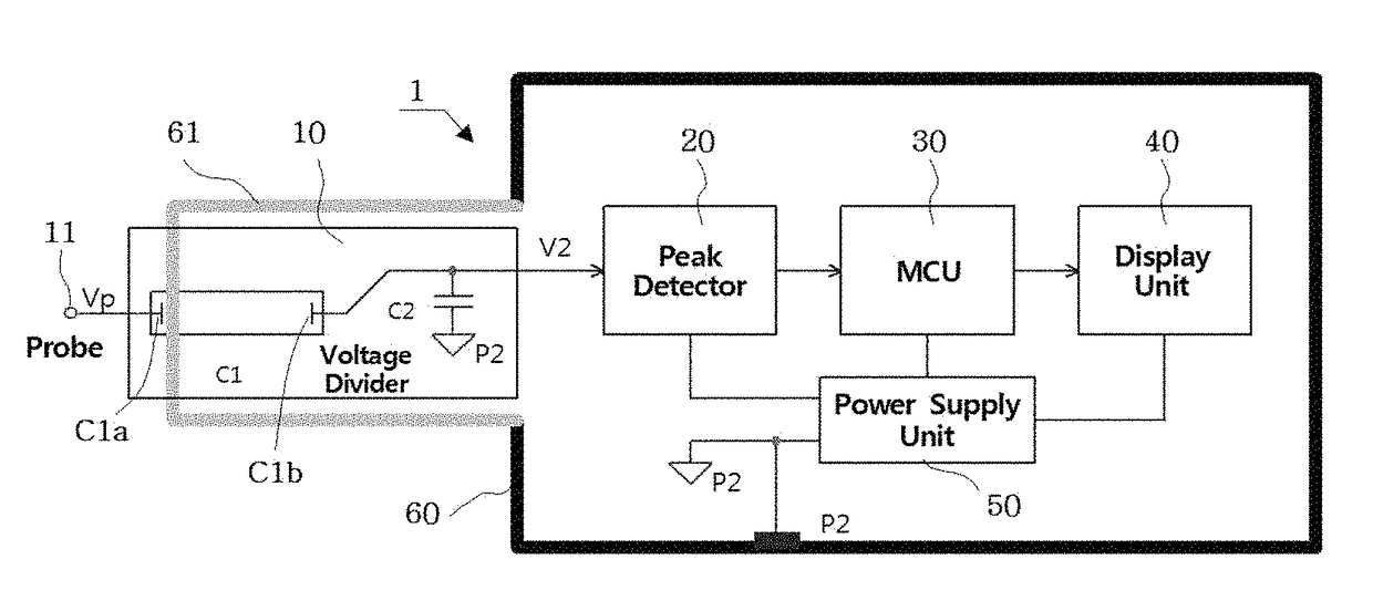
[0053]Referring to FIG. 3, in the first embodiment, the electric fence voltmeter 1A includes:

[0054]a cylindrical body case 60 of which one side has an opening;

[0055]a cylindrical sensor case 61 connected to the opening of the body case 60 to protrude from the body case 60;

[0056]a printed circuit board 70 in which a part of the voltage divider 10, the peak detector 20, the MCU 30, the display unit 40, and other electronic parts are assembled; and

[0057]a power supply unit 50 for supplying electric power to the elements constituting the voltmeter.

[0058]The capacitor C1 of the voltage divider 10 has the first electrode C1a placed on the outer end of the sensor case 61 in the form of a surface electrode, and the second electrode C1b placed in the inside of the sensor case 61 in the form of a surface electrode that is spaced oppositely to the first electrode C1a at a prede...

second embodiment

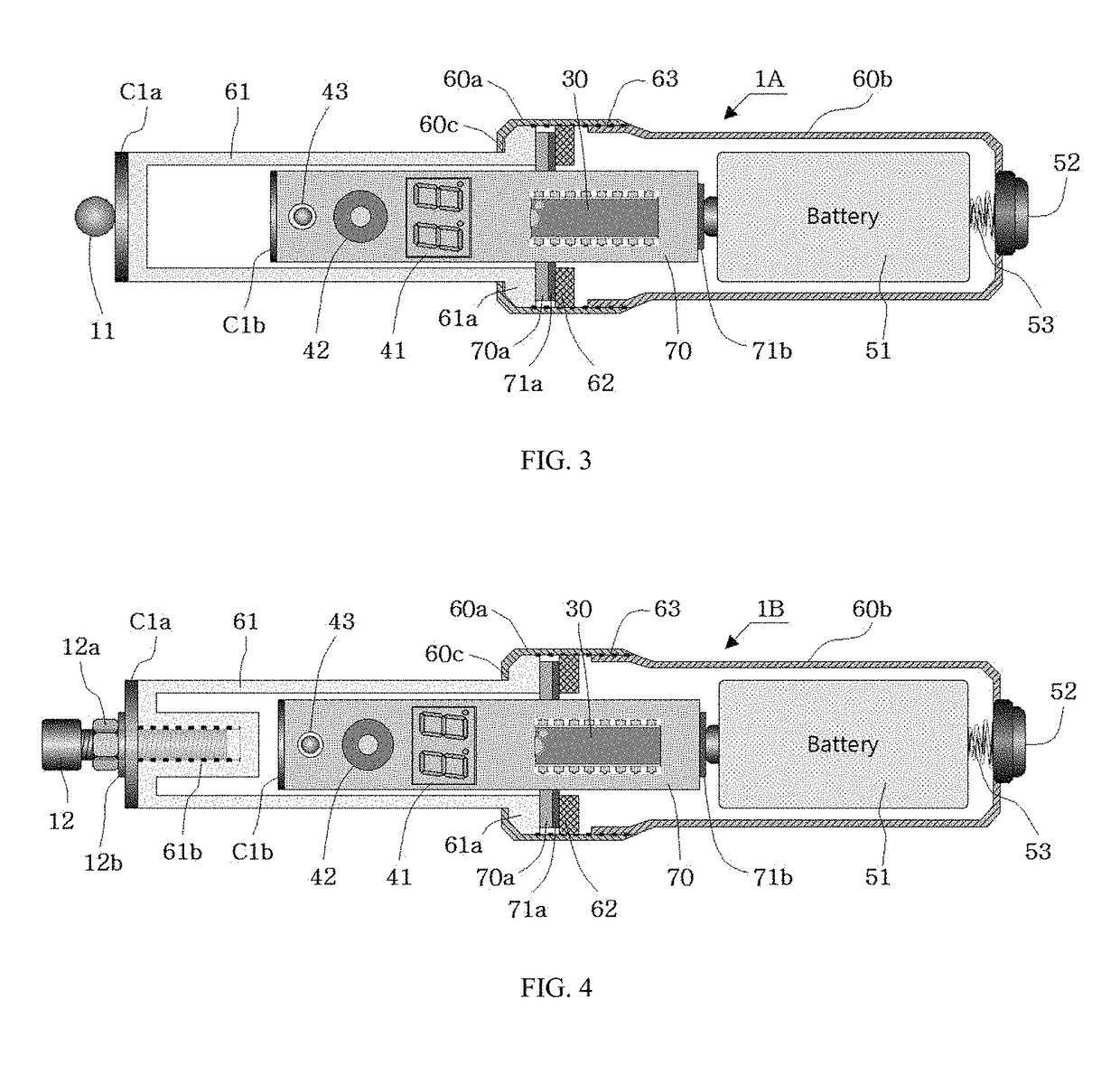
[0069]Meanwhile, referring to FIG. 4, in the present discloser, the voltmeter 1B has a means for adjusting the capacitance of the capacitor C1 to set up the voltage division ratio (Rd). The capacitance of the capacitor C1 can be adjusted by modulating the equivalent distance between the first electrode C1a and the second electrode C1b of the capacitor C1.

[0070]That is, in the second embodiment, the electric fence voltmeter 1B further includes:

[0071]a bolt shaped capacitance adjuster 12 made of a conductive material screwed through a hole formed at the center of the first electrode C1a of the capacitor C1 into a threaded blind hole 61b formed inside of the sensor case 61 directed to the second electrode C1b; and

[0072]a locking means 12a for locking the screw coupling of the capacitance adjuster 12 and the threaded blind hole 61b at an arbitrary position,

[0073]on the electric fence voltmeter 1A.

[0074]The head of the bolt shaped capacitance adjuster 12 may also be used as the probe 11 ...


PUM


Abstract

The present disclosure relates to a hand-held voltmeter measuring a peak voltage of a high voltage pulse applied to an electric fence. The voltmeter includes a body case of which one side has an opening, a sensor case protruded from the opening of the body case, a voltage divider disposed over the inside and the outside of the sensor case for dividing the high voltage pulse into a low divided voltage, a peak detector for detecting the peak voltage of the divided voltage, a display unit for displaying the peak voltage, and an MCU for controlling the input and the output of the elements constituting the voltmeter. According to the present disclosure, an electric fence voltmeter that measures the peak voltage accurately without need to make a ground connection to the earth, and has a low risk of an electric shock during a measurement is provided.

Description

BACKGROUND OF THE INVENTIONField of the Invention[0001]The present disclosure relates to a voltmeter for measuring the peak voltage of a high voltage pulse applied to an electric fence. More particularly, the present disclosure relates to the electric fence voltmeter having high measurement coupling factor that eliminates the need for connecting the ground terminal of the voltmeter to the earth. The high coupling factor can be achieved by optimizing the distribution of various stray capacitances acting on the voltmeter.Related Art[0002]An electric fence prevents the intrusion of wild animals, or the escape of livestock cultivated in the fence. A pulse shaped high voltage generated from an energizer is applied between the earth and the fence wire which is supported by the insulators installed around fence posts. If an animal is in contact with the fence wire, a strong pain is caused by an electric shock due to the circulating current flowing through the animal.[0003]Most of the elect...

Claims


Application Information

Patent Timeline
Patent Type & Authority Patents(United States)
IPC IPC(8): G01R1/00G01R13/00G01R19/04G01R15/00
CPCG01R19/04G01R13/00G01R1/06788G01R19/0084G01R1/067G01R15/04G01R15/144G01R15/16G01R29/02
Inventor CHO, BYUNG-HAK
Owner CHO BYUNG HAK
Why Eureka
Try Eureka