Rounded projectiles for target disruption

a technology of projectiles and target disruption, applied in the direction of projectiles, ammunition projectiles, weapons, etc., can solve the problem of not being practicable, or even possible, to achieve a perpendicular shot on targ

Active Publication Date: 2022-08-23
THE UNITED STATES OF AMERICA AS REPRESENTED BY THE FEDERAL BUREAU OF INVESTIGATION DEPT OF JUSTICE
View PDF83 Cites 0 Cited by
  • Summary
  • Abstract
  • Description
  • Claims
  • Application Information

AI Technical Summary

Benefits of technology

[0005]Included herein are rounded projectiles, projectile cartridges comprises the rounded projectiles, and methods of disrupting an explosive device (such as an improvised explosive device, IED) with a rounded projectile using a propellant driven disrupter (PDD), also known as a dearmer. The rounded projectiles and projectile cartridges disclosed herein are compatible with a wide variety of PDDs and barrels, including smooth bore barrels and rifled bore barrels. The rounded projectiles are accurate, precise, and can penetrate barriers, including steel barriers, and ultimately disrupt an explosive device without initiating or detonating an explosive material of the explosive device. The rounded projectile follows the same trajectory during flight and notably during penetration of the explosive device with minimal deviation or error. Additional benefits include the lack of secondary projectiles being propelled ahead of the projectile, such that explosive is not initiated / detonated by any secondary projectiles, or at least any such projectiles are minimal, with well-controlled direction so that there is no reasonable risk of inadvertent detonation. In some embodiments, the rounded projectile forms a composite projectile via solid state welding with a portion of the hazardous device's barrier.
[0007]Aspects of the invention include a method for disrupting an explosive device using a propellant driven disrupter (PDD), the method comprising the steps of: loading a rounded projectile (RP) into a disrupter barrel of the PDD; aiming the PDD at a target portion of the explosive device; propelling the RP out of the barrel and toward the target portion of the explosive device; wherein the RP travels along a linear trajectory defined by a barrel longitudinal axis extending between a barrel muzzle end and the target portion; impacting the RP with a barrier portion of the explosive device, the barrier portion being between the barrel muzzle end and the target portion along said linear trajectory; wherein the step of impacting comprises forming a composite projectile via a solid state weld between the barrier portion of the explosive target to a RP distal end, and avoids generation of spalls and fragments into the explosive device; and traversing the composite projectile a penetration distance through the explosive device; wherein the composite projectile traverses the penetration distance along said linear trajectory, such that the RP follows said linear trajectory during the steps of propelling, impacting, and traversing; and disrupting the explosive device without detonating an explosive of the explosive device.
[0026]The rounded projectiles are preferably used with a wadding or a liner. A wadding helps to keep the RP centered in the barrel, especially in the case of a spherical projectile and a smooth bore. The wadding preferably also acts as a gas seal and preferably keeps the shell internal components behind the projectile in flight by not allowing them to pass through the gap between the bore and the RP. The wadding preferably can be made of a low friction material or a self-lubricating textile. For example, textile wadding can be constructed from silk, cotton, synthetic fibers, Kevlar™ Dyneema™, a similar material, or any combination of these. The reduced friction results in increased projectile velocity. A liner, if used, also helps to keep the projectile centered but may have additional benefits of minimizing or eliminating creation of secondary projectiles by minimizing or eliminating pieces of the RP coming off due to interaction with the rifling.
[0034]Preferably for any of the methods, rounded projectiles, and / or projectile cartridges disclosed herein, the RP is formed of one or more steel alloys, a chromium steel, S2 steel, S4 steel, C300 steel, C350 steel, other tool steels, armor steel, one or more titanium alloys, Ti-6Al-4V, one or more nickel alloys, one or more tungsten alloys, or any combination of these. Preferably for any of the methods, rounded projectiles, and / or projectile cartridges disclosed herein, the RP is characterized by a tensile strength selected from the range of 160 KSI to 390 KSI and a Rockwell hardness selected from the range of C40 to C70. Optionally for any of the methods, rounded projectiles, and / or projectile cartridges disclosed herein, the RP is characterized by a durameter selected from the range of 70 to 90. Optionally for any of the methods, rounded projectiles, and / or projectile cartridges disclosed herein, RP is characterized by a density selected from the range of 4.5 to 16 g / cm3. Optionally for any of the methods, rounded projectiles, and / or projectile cartridges disclosed herein, the RP is chemically, physically, and / or magnetically adhered to the first cylindrical shell. Optionally for any of the methods, rounded projectiles, and / or projectile cartridges disclosed herein, the RP is configured for use with a smooth PDD barrel or configured for use with a smooth and rifled PDD barrel. Optionally for any of the methods, rounded projectiles, and / or projectile cartridges disclosed herein, the RP is configured for use with a smooth PDD barrel. Optionally for any of the methods, rounded projectiles, and / or projectile cartridges disclosed herein, the RP is configured for use with a smooth and a rifled PDD barrel. Optionally for any of the methods, rounded projectiles, and / or projectile cartridges disclosed herein, the RP has a patterned or roughened outer surface. Optionally for any of the methods, rounded projectiles, and / or projectile cartridges disclosed herein, the RP has a knurled outer surface, a brushed or tumbled outer surface, a pitted outer surface, or a polished outer surface. Optionally for any of the methods, rounded projectiles, and / or projectile cartridges disclosed herein, the RP has an outer rough surface characterized by a surface roughness characterized by each of a spacing between surface texture peaks and a height between surface texture and surface texture valleys selected from the range of 0.0001″ to 0.01″. Optionally for any of the methods, rounded projectiles, and / or projectile cartridges disclosed herein, the RP comprises a case hardened outer layer. Optionally for any of the methods, rounded projectiles, and / or projectile cartridges disclosed herein, the RP is a composite comprising a core material and an outer layer that surrounds the core material selected to: avoid target barrier secondary fragments or spall; minimize interaction between shell elements and target, and have a decreased risk of unwanted shock initiation of a target explosive. Optionally for any of the methods, rounded projectiles, and / or projectile cartridges disclosed herein, the RP is formed of a material or materials configured to be non-frangible during use, such that the RP is not fractured or disintegrated upon impact with a metal barrier of the explosive device.

Problems solved by technology

This oblique angle aspect is relevant because in real-world situations, it may not be practical, or even possible, to achieve a perpendicular shot on target.

Method used


Image

  • Rounded projectiles for target disruption
  • Rounded projectiles for target disruption
  • Rounded projectiles for target disruption

Examples


example 1

rojectile (RP) Description

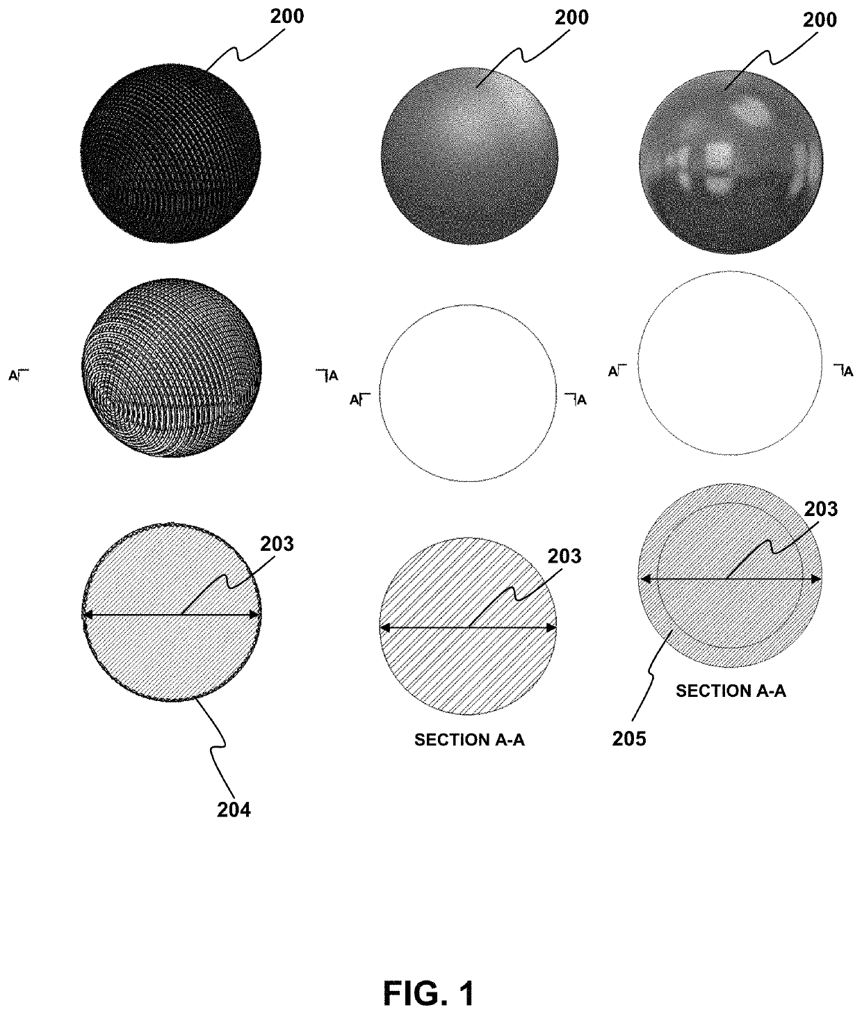
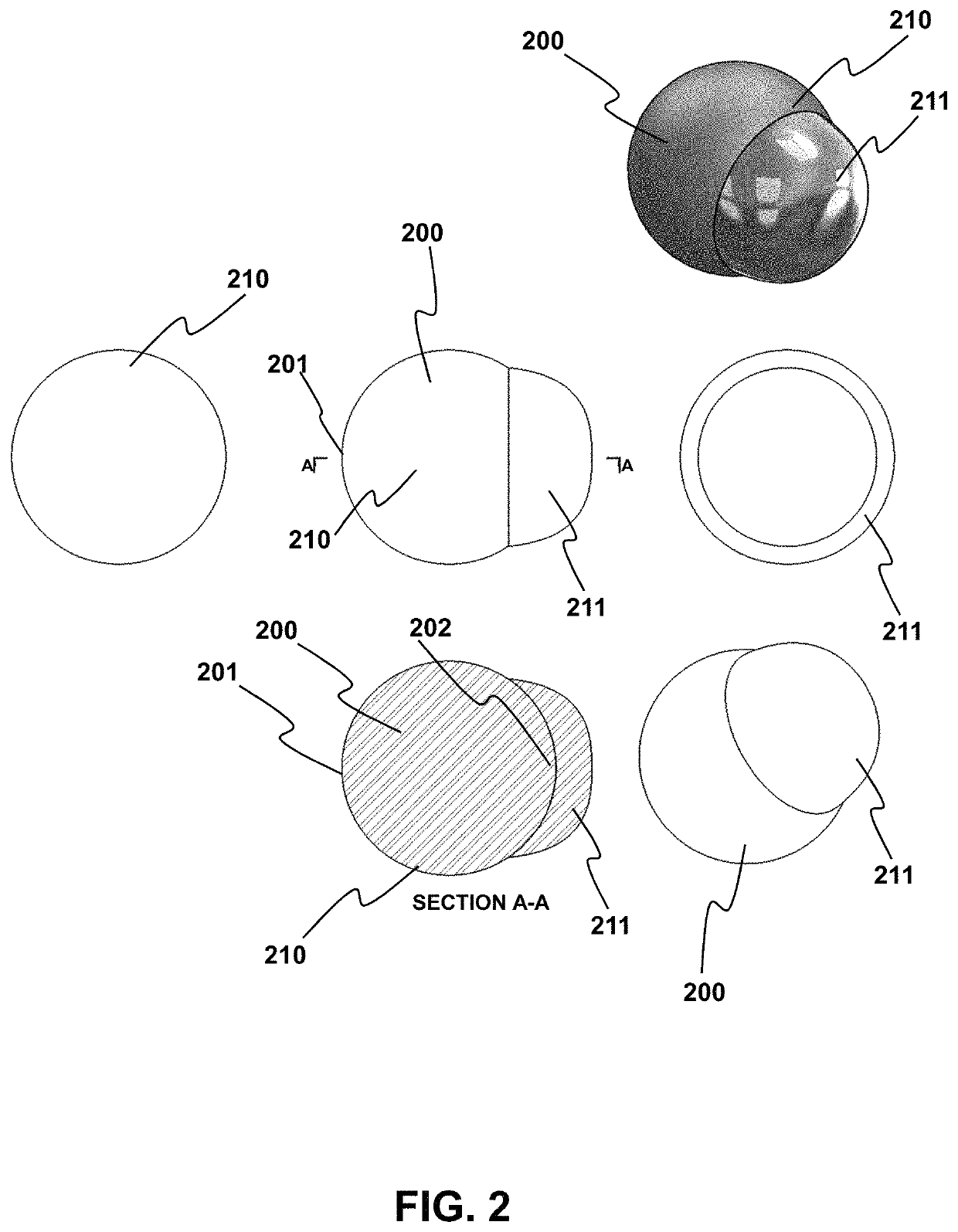
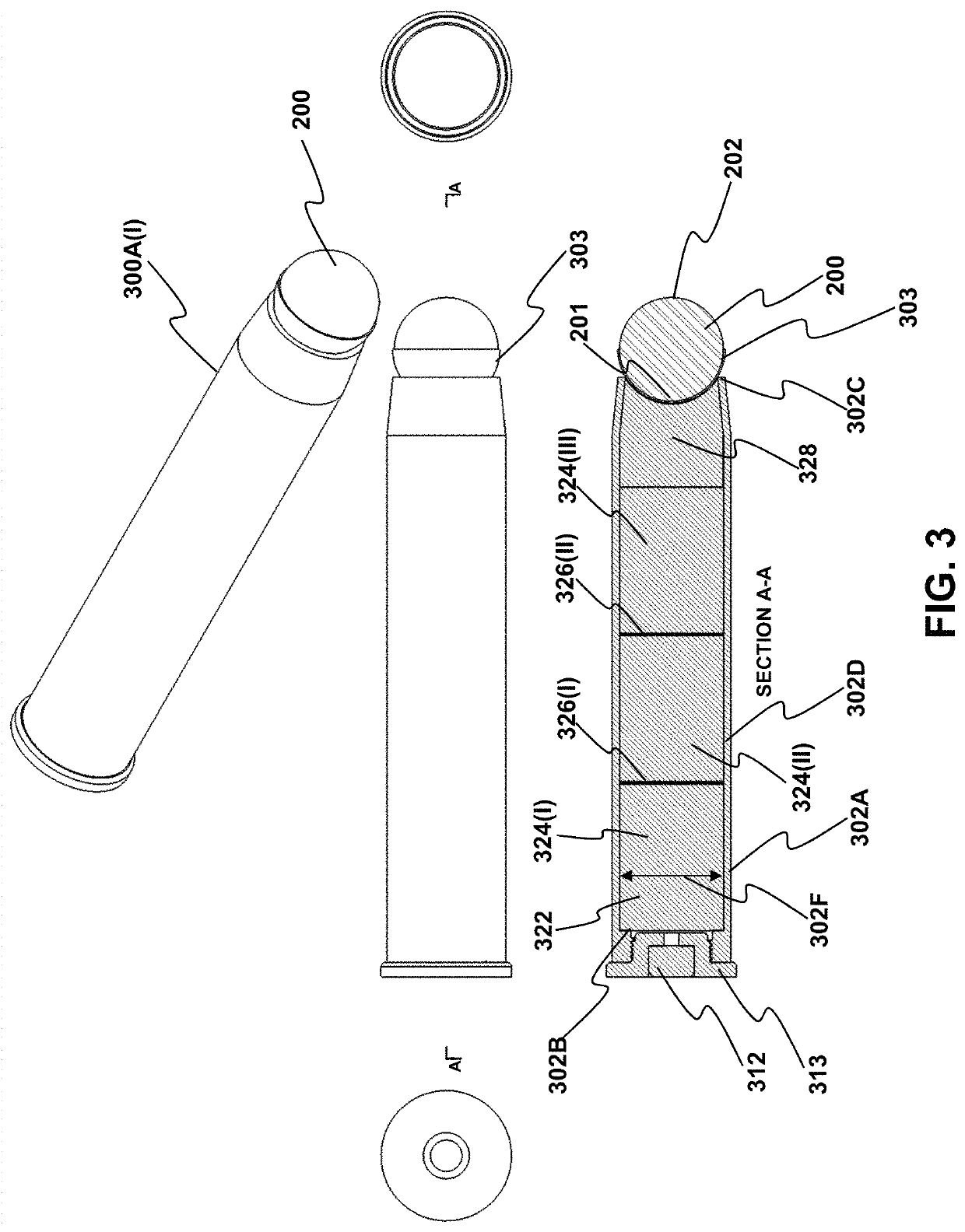
[0098]Described in this example are embodiments of a rounded projectile (RP), such as RP 200, which is also interchangeably referred to herein as a Supersphere (or supersphere). Also described are projectile cartridges, such as projectile cartridge 300A, having rounded projectiles, or Superspheres, and method of using these. The Supersphere, is an interchangeable disrupter / dearmer spherical projectile and cartridge system for precise disablement of an explosive device, such as explosive device 120, or ordnance structural components. A spherical shape is stable in flight and cannot pitch, yaw, tumble, nor wobble, all of which cause projectiles to veer off a trajectory. Superspheres (i.e., RPs) described herein are designed to be accurate after perforating single or multiple barriers and precisely destroy fuzing components or structures of interest inside of an improvised explosive device (IED) or military ordnance. Alternatively, they can be used in breachin...

example 2

rojectile as a Fluid Plug

[0124]Any of the rounded projectiles provided herein may be used to seal a distal end of fluid, such as water, that is positioned in a disrupter barrel. In this manner, the rounded projectile acts as a cap to ensure the fluid does not leak out of the barrel. A preferred rounded projectile is a synthetic rubber spherical ball that is of sufficiently high strength such that the ball can withstand the exerted forces during use without visible damage. In this manner, the rounded projectile plus ReVJeT configuration (e.g., water in a portion of the barrel) provides a number of important functional benefits, including the ability to reliably penetrate a larger barrier layer thickness, good performance at a greater standoff distance, and a reduced risk of impact initiation of explosives in an IED. For at least these reasons, it is advantageous to use a rounded projectile as an improved water seal (e.g., “hydrosphere”) for disruption of medium to hard shell (barrier...

example 3

ngle of Attack on Target

[0128]In real-world situations, it is not realistic to always have an exact perpendicular line of attack between the liquid jet and solid projectile relative to the target, as illustrated in FIG. 24.

[0129]Schematic illustrations of impact mechanics for a perpendicular and oblique angle of attack are provided in FIGS. 26-31 and 32-39, respectively. Illustrated is a rounded projectile, barrier layer, desired contact point internal relative to the barrier layer. The trajectory of the rounded projectile (RP) is indicated by the arrow, with D representing the distance between the internal surface of the barrier layer and point of aim within the target.

[0130]FIG. 26 illustrates the RP with a perpendicular pre-impact trajectory.

[0131]FIG. 27 illustrates the RP initial impact with the barrier layer, where the impact pressure exceeds the barrier layer material's elastic-plastic limit, thereby forming a channel inside the barrier layer that effectively “guides” the RP ...


PUM


Abstract

Provided are methods and related devices for disrupting an explosive device using a propellant driven disrupter (PDD) that propels a rounded projectile (RP) toward an explosive device. The RP travels along a linear trajectory and impacts the target, including a barrier portion of the explosive device. The impacting between the RP and barrier forms a composite projectile via a solid state weld between a portion of the barrier and the RP distal end, thereby minimizing or avoiding spall and fragment generation into the explosive device. The projectile traverses a penetration distance along the linear trajectory, or a defined-angle relative thereto, to disrupt the explosive device without unwanted explosive detonation.

Description

CROSS-REFERENCE TO RELATED APPLICATIONS[0001]This application claims the benefit of and priority to U.S. Provisional Patent Application No. 63 / 033,475 filed Jun. 2, 2020, which is specifically incorporated by reference in its entirety to the extent not inconsistent herewith.STATEMENT OF GOVERNMENT INTEREST[0002]The inventions described herein were invented by employees of the United States Government and thus, may be manufactured and used by or for the U.S. Government for governmental purposes without the payment of royalties.BACKGROUND OF INVENTION[0003]In the art of hazardous devices access and disablement, including explosive ordnance disposal, a common tool, particularly for neutralizing improvised explosive devices (IEDs), is the propellant driven disrupter. A propellant driven disrupter may be used to fire a solid projectile or a jet of fluid at an IED with the goal of disrupting the explosive and avoiding its detonation. A solid projectile may penetrate tougher casing materia...

Claims


Application Information

Patent Timeline
Patent Type & Authority Patents(United States)
IPC IPC(8): F42B33/06F42B12/76F42B12/74F41A21/02
CPCF42B33/06F41A21/02F42B12/745F42B12/76F41A21/482F42B12/74
Inventor VABNICK, IAN B.
Owner THE UNITED STATES OF AMERICA AS REPRESENTED BY THE FEDERAL BUREAU OF INVESTIGATION DEPT OF JUSTICE
Why Eureka
Try Eureka