End cap for a tubular light source

a tubular light source and end cap technology, applied in the direction of fixed installation, coupling device connection, lighting and heating apparatus, etc., can solve the problem of unintentional push of the installer, and achieve the effect of improving safety and facilitating safe installation of the tubular light sour

Active Publication Date: 2017-03-07
KONINKLIJKE PHILIPS ELECTRONICS NV
View PDF13 Cites 0 Cited by
  • Summary
  • Abstract
  • Description
  • Claims
  • Application Information

AI Technical Summary

Benefits of technology

[0005]In view of the aforementioned and other drawbacks of prior art, it is an object of the present invention to improve the safety when installing a tubular light source, in particular it is an object to provide an end cap for a tubular light source comprising LEDs, the end cap further comprising a safety switch to facilitate safe installation of the tubular light source in a fixture.
[0007]The present invention is based on the realization that a safety switch for a tubular light source may advantageously be integrated into the end cap of the tube and that the safety switch preferably is automatically closing an electrical circuit by forming a conductive path between the socket and the tubular light source during installation of such a light source. In particular, in some tubular light sources, the internal circuitry is arranged so that the light source may provide a conductive path from the connector pins in one end portion of an elongate tube to connector pins in the opposite end portion even if the light source is not active contrary to what was possible in conventional fluorescent light tubes. In other words, it is possible that mounting one end portion of the tubular light source in the socket of the lighting fixture leads to the connector pins in the opposite end portion carrying a live voltage. In particular, having a push-in mechanism arranged on the end cap may cause the installer to unintentionally push the safety mechanism during installation of the tubular light source, thereby engaging the electrical circuit. By having a switch which automatically closes an electrical circuit only when the connector pins are out of reach for the installer, the risk for the installer of receiving an electrical shock when installing a tubular light source is significantly reduced.
[0008]In one embodiment, the conductive path may advantageously be formed at a second side of the switch element, wherein the second side is arranged inside of the housing. Arranging the switch mechanism inside of the housing provides additional safety as any conductive part is out of reach. The conductive path may for example be formed by aligning a conductive element with the two connector pins, wherein the conductive element is electrically connected to the tubular light source. Such a switch arrangement ensures that the connector pins are only electrically connected after the tubular light source has been installed in the fixture.
[0010]In one embodiment, the tubular light source may advantageously comprise a plurality of LEDs. LEDs are advantageously used as a replacement for fluorescent light sources as LED are more power efficient, smaller in size and have a longer life-length as well as being more environmental friendly. Thereby, using LEDs may improve a tubular light source both with regard to environmental aspects and to the overall economy of the light source as power consumption is reduced and as fewer replacements are needed.

Problems solved by technology

In particular, having a push-in mechanism arranged on the end cap may cause the installer to unintentionally push the safety mechanism during installation of the tubular light source, thereby engaging the electrical circuit.

Method used


Image

  • End cap for a tubular light source
  • End cap for a tubular light source
  • End cap for a tubular light source

Examples


Embodiment Construction

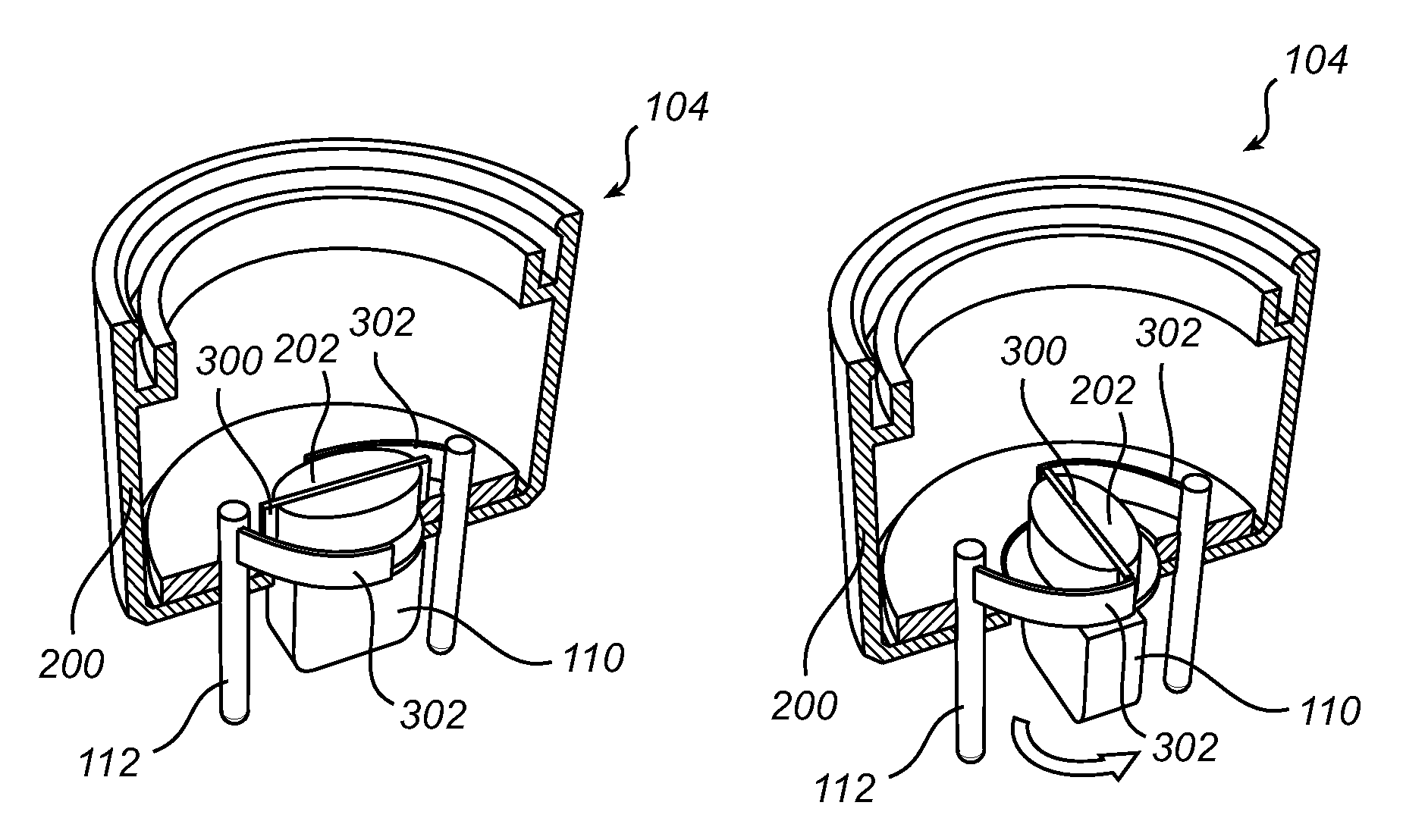
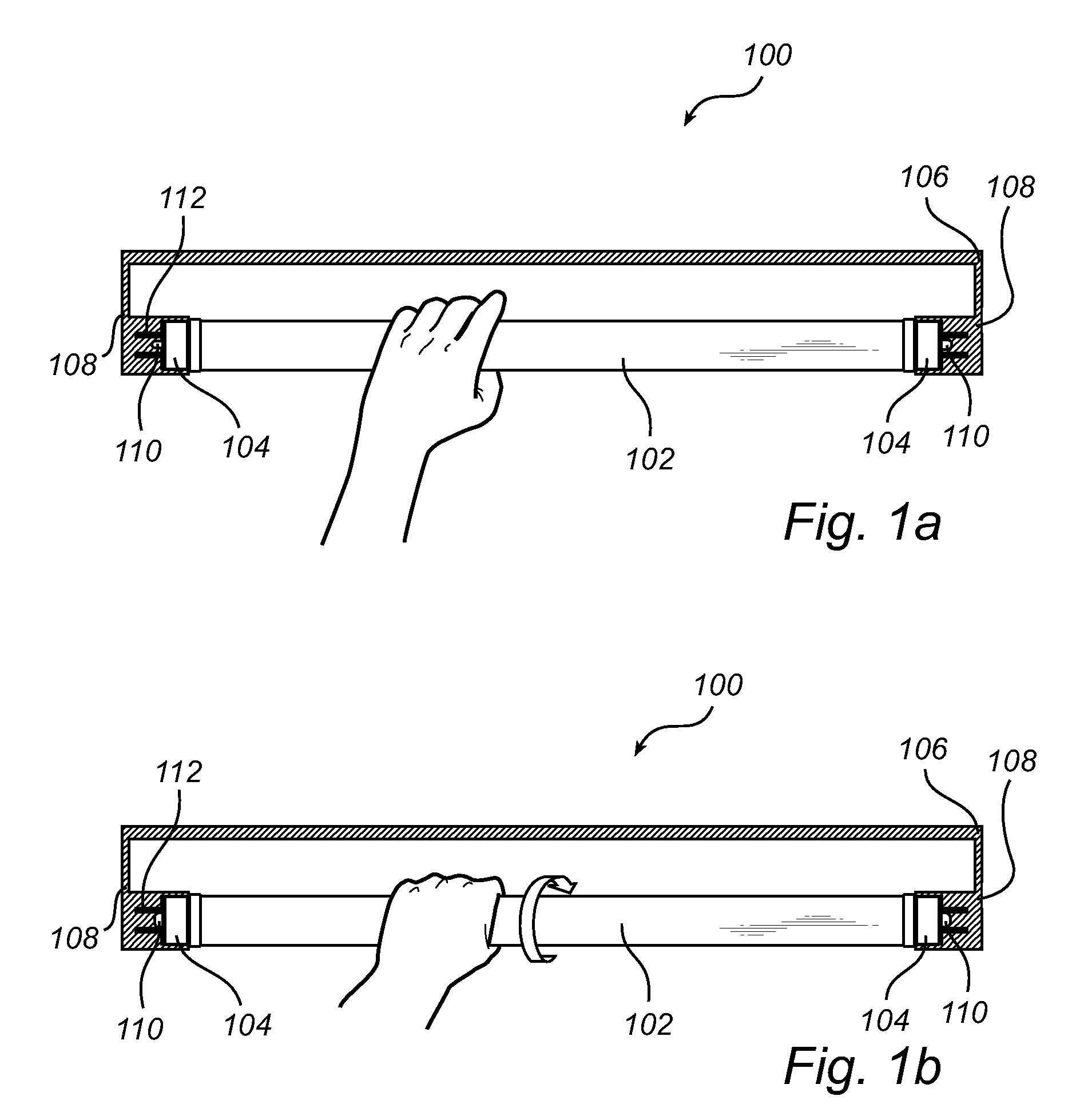
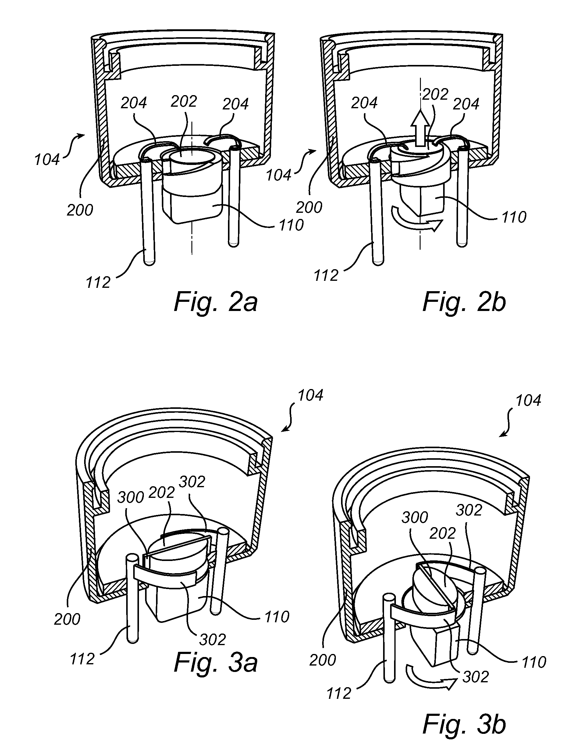
[0017]The present invention will now be described more fully hereinafter with reference to the accompanying drawings, in which currently preferred embodiments of the invention are shown. This invention may, however, be embodied in many different forms and should not be construed as limited to the embodiments set forth herein; rather, these embodiments are provided for thoroughness and completeness, and fully convey the scope of the invention to the skilled person. Like reference characters refer to like elements throughout.

[0018]In order for an electrically powered device to be powered a closed circuit through which electrical current can flow needs to be established. Typical examples of electrically powered devices include, but are not limited to, light sources, luminaires, LED retrofits of linear TL tubes, and the like. Electrically powered devices are provided with electrical connecting means by which the electrically powered devices can be electrically connected to an interface ...


PUM


Abstract

An end cap (104) for a tubular light source (102), the tubular light source (102) being configured to be arranged in a lighting fixture (106) comprising at least one socket (108), wherein the end cap (104) comprises a housing (202), two connector pins (112) at least partly arranged on an outside of the housing (202) and adapted to fit in the socket, and a switch assembly comprising a switch element (110) arranged in between the two connector pins (112) and at least partly protruding from an opening in the housing (202), wherein a first side of the switch element (110) is adapted to fit into a slot in a socket (108) and wherein the switch assembly is configured to form a conductive path between the socket (108) and the tubular light source (102) through an axial rotation of the switch element (110) in relation to the housing (202) as the tubular light source (102) is rotatably mounted in the fixture (106).

Description

FIELD OF THE INVENTION[0001]The present invention relates to an end cap for a tubular light source, and in particular to an end cap enabling safe installation of such a tubular light source.BACKGROUND OF THE INVENTION[0002]Fluorescent lighting tubes are commonly used in a large range of lighting systems as a result of advantages such as longer life time and better luminous efficiency compared to incandescent lamps. However, in the continuous effort to reduce power consumption, it is desirable to replace conventional light tubes with still more energy efficient and environmental friendly alternatives. One such alternative is to use LED tubular light sources having a plurality of LED's arranged in a tube similar to the fluorescent tube. In order to facilitate a transition from fluorescent tube lights to LED tubular light sources, the LED tubular light sources should be configured to be mounted in already existing fixtures for fluorescent light tubes. However, the electrical circuitry ...

Claims


Application Information

Patent Timeline
Patent Type & Authority Patents(United States)
IPC IPC(8): F21V23/04F21V25/04F21V23/06F21V19/00H01R33/94H01R33/96F21S8/00F21Y101/00
CPCF21V23/04F21K9/27F21V19/008F21V23/06F21V25/04H01R33/942H01R33/96F21S8/031F21Y2101/00F21Y2115/10F21K9/272
Inventor GIELEN, VINCENT STEFAN DAVIDBUKKEMS, PETER JOHANNES MARTINUS
Owner KONINKLIJKE PHILIPS ELECTRONICS NV
Why Eureka
Try Eureka