Systems and methods for direct emitter geolocation

a technology of direct emitter and geolocation, applied in direction finders using radio waves, instruments, measurement devices, etc., can solve the problems of low-snr emitter and overloaded environment, and conventional observable-based geolocation techniques are typically impossible, so as to facilitate visual identification of signal peaks and enhance the location of unknown emitter/s

Active Publication Date: 2016-06-28
L3HARRIS TECH INTEGRATED SYST LP
View PDF6 Cites 1 Cited by
  • Summary
  • Abstract
  • Description
  • Claims
  • Application Information

AI Technical Summary

Benefits of technology

[0006]In a further embodiment, partial timing structure and / or frequency structure information may be known about the signal modulation (e.g., if a SW is known to be active only at a discrete set of times or if a SW is known to move in frequency in a deterministic pattern) and may be employed to improve geolocation accuracy (e.g., if data is only collected at times and frequencies when the SW is known to be active, the interference of cochannel emitters may be reduced) without requiring a known reference emitter signal or complete knowledge of the signal modulation or transmitted SW (e.g., a SW emitter may be known to employ a time-division-multiple-access scheme, which may provide information on when a signal is active but not what signal is being transmitted when the SW emitter is active).
[0011]Advantageously, in one exemplary embodiment, the disclosed systems and methods may be implemented to locate one or more low power emitters (e.g., having an emitter power that is lower than or under the noise floor throughout the integration) using a single SW signal collection platform (e.g., aircraft or other suitable mobile platform such as spacecraft, satellite, ship, wheeled vehicle, submarine, etc.) that moves relative to the emitter location / s. In another exemplary embodiment, the disclosed systems and methods may be implemented to locate multiple cochannel (or co-frequency) emitters that all simultaneously transmit on the same frequency. The disclosed systems and methods may be further employed in another exemplary embodiment to detect multiple emitters in a manner that is not limited by the number of antenna elements, e.g., by using overloaded array processing to locate more SW signal emitters than the number of elements present in an interferometry array of a SW signal collection platform. These features may be combined in one exemplary embodiment to achieve overloaded array cochannel processing to locate multiple low-power SW emitters. In a further embodiment, more than one SW signal collection platform may be employed to further enhance location of unknown emitter / s.
[0012]In another exemplary embodiment, direct geolocation of multiple emitters of unknown location may be achieved by performing an iterative serial nulling or cancellation process. Such a serial nulling process may include using an interferometer array on a moving signal collection platform to collect SW signal data that includes signals received from multiple cochannel emitters transmitting from unknown locations along the path of the moving collection platform (e.g., along an aircraft flight path). The collected SW data may be processed and mapped (or otherwise digitized and / or stored) in a manner that facilitates visual identification of signal peaks that represent potential emitter locations. Geolocations of the multiple emitters may be sequentially identified and determined.

Problems solved by technology

Conventional observable-based geolocation techniques typically become impossible with low-SNR emitters and overloaded environments (i.e., environments with more signals than antenna elements).

Method used


Image

  • Systems and methods for direct emitter geolocation
  • Systems and methods for direct emitter geolocation
  • Systems and methods for direct emitter geolocation

Examples


Embodiment Construction

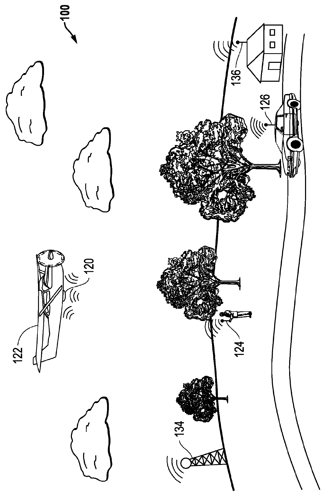
[0023]FIG. 1 illustrates one exemplary embodiment of a SW emissions environment 100 (in this case a radio frequency (RF) communication environment) in which multiple ground-based emitters 124, 126, 134 and 136 at unknown locations are transmitting RF signals of interest. In the illustrated embodiment of FIG. 1, unknown emitters 124 and 126 are mobile emitters that may be moving and / or stationary while transmitting. In this example, mobile emitter 124 is carried by a human being, and mobile emitter 126 is supported by a moving vehicle that results in emitter transmission from changing location. Unknown emitters 134 and 136 are stationary emitters that transmit emitter signals from respective fixed locations as shown.

[0024]It will be understood that the disclosed systems and methods may be practiced in SW signal emission environments in which any type, number and / or combination of different types of SW emitters are emitting on one or more frequencies. It will be understood that a SW e...


PUM


Abstract

Systems and methods are disclosed for locating signal wave (SW) emitter / s using at least one moving signal collection platform. The disclosed systems and methods may be employed in one embodiment to estimate the signal energy transmitted from a grid of locations (such as a map) using collected IQ data (or other raw data representation such as IQ data covariance matrix), and without requiring computation of any intermediate geolocation-observable measurements (such as angle-of-arrival, direction-of-arrival, etc.). In a further embodiment, the disclosed systems and methods may be implemented in a blind manner (i.e., transmitted emitter signal / s are unknown and processed blindly) to geolocate SW emitters using a single SW signal collection platform (e.g., at relatively large standoff distances in some implementations) without relying on a known signal modulation or operation of multiple simultaneous SW signal collection platforms.

Description

[0001]This application claims the benefit of U.S. Provisional Patent Application No. 61 / 818,829, filed on May 2, 2013 and entitled “Systems and Methods for Direct Emitter Geolocation”, which is incorporated herein by reference in its entirety for all purposes.FIELD OF THE INVENTION[0002]This invention relates to emitter geolocation.BACKGROUND OF THE INVENTION[0003]Emitter geolocation methods exist that rely either on use of multiple separate simultaneous signal collection platforms (e.g., separate aircraft), or rely on knowledge of the signal modulation structure of an emitter signal. For example, a direct approach to geolocation that requires knowledge of emitter signal modulation has been conventionally employed. Such a direct approach does not require determination of an intermediate geolocation observable measurement such as from time difference of arrival (TDOA), frequency difference of arrival (FDOA), direction of arrival (DOA), etc. However, such a conventional direct geoloca...

Claims


Application Information

Patent Timeline
Patent Type & Authority Patents(United States)
IPC IPC(8): G01S3/02G01S5/02G01S5/04
CPCG01S5/02G01S5/0249G01S2205/03
Inventor WESTCOTT, BRYAN L.STANNERS, STEVEN P.
Owner L3HARRIS TECH INTEGRATED SYST LP
Why Eureka
Try Eureka