Slant angle vent plate pattern and method

a venting pattern and angle technology, applied in the field of electromechanical devices, can solve the problem that the opening size of the venting pattern must be sufficiently small, and achieve the effect of maximizing air flow and available surface area

Active Publication Date: 2016-06-28
AVAGO TECH INT SALES PTE LTD
View PDF15 Cites 3 Cited by
  • Summary
  • Abstract
  • Description
  • Claims
  • Application Information

AI Technical Summary

Benefits of technology

[0010]As the slant angle venting plate is slanted, the available surface area in which to form the slant angle vent plate pattern is increased as compared to the vertical chassis base sidewall. In this manner, the surface area of slant angle vent plate pattern is maximized thus maximizing air flow through the electronic enclosure and cooling of the electronic components contained therein.

Problems solved by technology

However, the size of the openings of the venting pattern must be sufficiently small to provide adequate electromagnetic interference (EMI) shielding.

Method used


Image

  • Slant angle vent plate pattern and method
  • Slant angle vent plate pattern and method
  • Slant angle vent plate pattern and method

Examples


Embodiment Construction

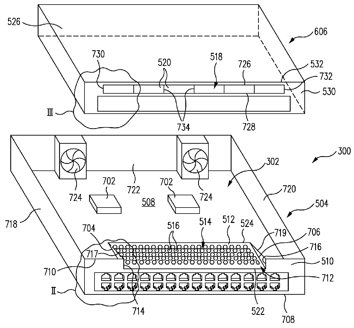
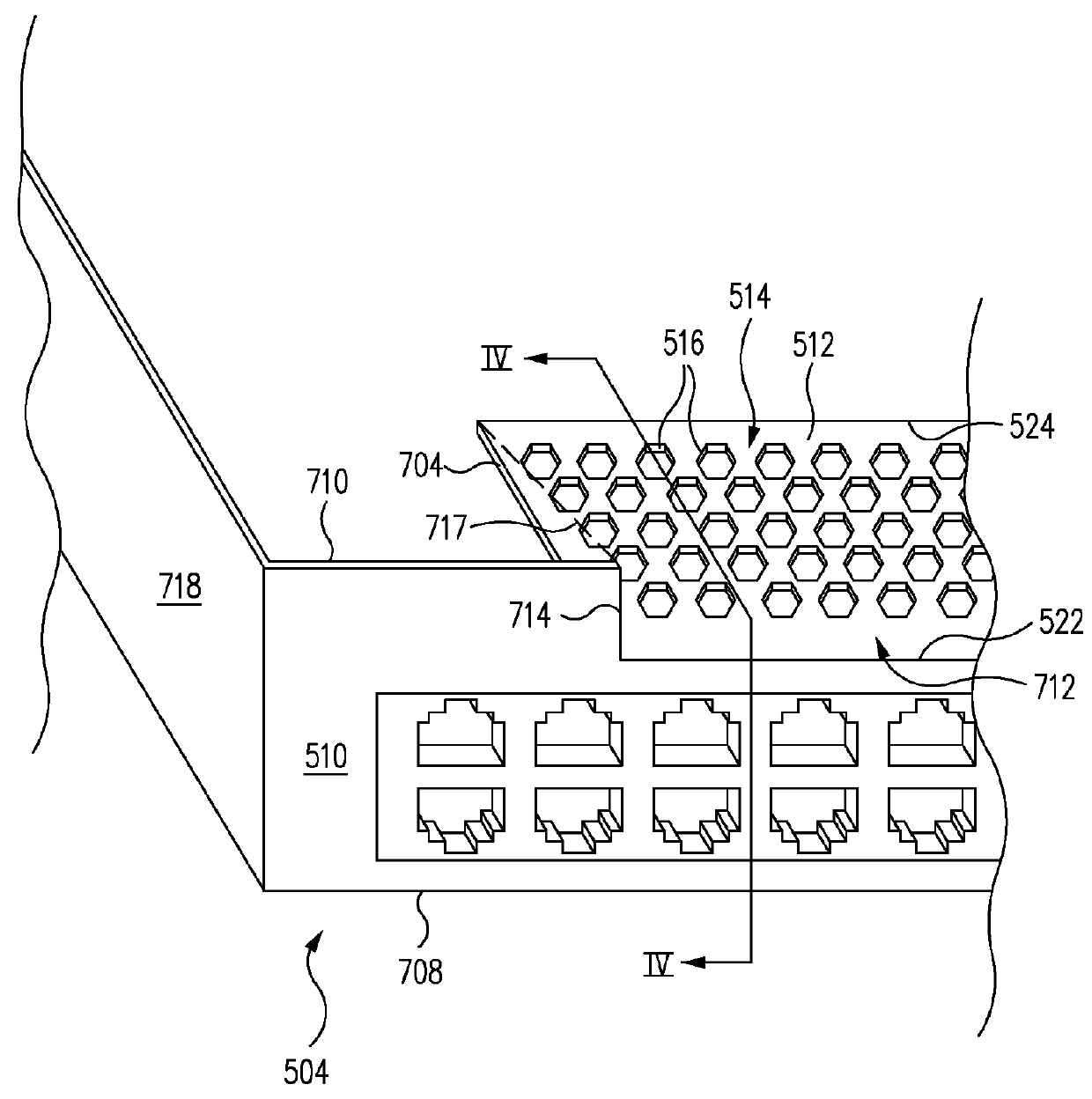
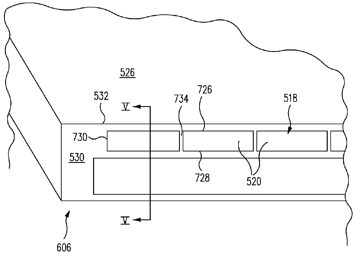
[0020]FIG. 1 is a front exploded perspective view of an electronic device 300 having a slant angle vent plate pattern 514 in accordance with one embodiment. FIG. 2 is an enlarged view of the region II of a chassis base 504 of electronic device 300 of FIG. 1 in accordance with one embodiment. FIG. 3 is an enlarged view of the region III of a chassis cover 606 of electronic device 300 of FIG. 1. FIG. 4 is a cross-sectional view along the line IV-IV of chassis base 504 of FIG. 2 in accordance with one embodiment. FIG. 5 is a cross-sectional view along the line V-V of chassis cover 606 of FIG. 3 in accordance with one embodiment. FIG. 6 is a cross-sectional view of electronic device 300 of FIG. 1 assembled in accordance with one embodiment.

[0021]Referring now to FIGS. 1-6 together, electronic device 300, e.g., a switch, includes an electronic enclosure 302 including chassis base 504 and chassis cover 606. Chassis base 504 includes a horizontal chassis base plate 508 and a vertical chass...


PUM


Abstract

An electronic device includes a chassis base and a chassis cover which define an electronic enclosure. The chassis base includes a slant angle venting plate extending at an angle from a chassis base sidewall of the chassis base. The slant angle venting plate has a slant angle vent plate pattern formed therein. Further, the chassis cover includes a chassis cover venting pattern covering the slant angle vent plate pattern. As the slant angle venting plate is slanted, the available surface area in which to form the slant angle vent plate pattern is maximized thus maximizing air flow through the electronic enclosure.

Description

RELATED APPLICATIONS[0001]This application claims the benefit of U.S. Provisional Application No. 61 / 898,331 filed on Oct. 31, 2013, entitled “SLANT ANGLE PERFORATION VENTING PATTERN AND METHOD” of Pinlin Zhuang, which is incorporated herein by reference in its entirety.BACKGROUND[0002]1. Field[0003]The present application relates to the field of electronics, and more particularly, to structures for enhancing air flow through an electronic device and related methods.[0004]2. Description of the Related Art[0005]An electronic device typically includes a plurality of electronic components contained within an electronic enclosure. During use, these electronic components generate heat, which must be removed from the electronic enclosure.[0006]In one example, the electronic enclosure includes vertical sidewalls, i.e., that are perpendicular to a base of the electronic enclosure. A venting pattern is formed in one of the vertical sidewalls to allow air flow therethrough. This is an example...

Claims


Application Information

Patent Timeline
Patent Type & Authority Patents(United States)
IPC IPC(8): H05K7/20H05K9/00
CPCH05K7/20145H05K9/0041H05K7/20181
Inventor ZHUANG, PINLIN
Owner AVAGO TECH INT SALES PTE LTD
Why Eureka
Try Eureka