Resonant signal analysis-based inspection of rail components

a technology of resonance signal and component, applied in the field of non-destructive inspection of vehicle components, can solve the problems of flat wear in one location on the wheel, overall change in k and thus in one or more relevant resonance frequencies, and none of these approaches have been used in field settings, so as to eliminate interference of vibrations from other wheels on the rail, easy to notice

Active Publication Date: 2016-07-12
INT ELECTRONICS MACHINES
View PDF30 Cites 29 Cited by
  • Summary
  • Abstract
  • Description
  • Claims
  • Application Information

AI Technical Summary

Benefits of technology

[0013]Use of a parabolic dish rather than a standard microphone to permit longer sample capture at greater standoff and superior signal-to-noise ratio.
[0015]Use of trending analyses on a captive fleet of wheels (e.g., in a transit setting) in conjunction with the above parametric model approach to directly track the condition of specific wheels throughout their lifetime. Trending can permit prediction of the expected changes in resonance for that specific wheel, and make any departures from that expectation much more easily noticed than, for example, a parametric model based only on a single idealized wheel or set of “average” wheels at a given state of wear.
[0016]Use of established databases (e.g., UMLER) to recognize wheel type, manufacturer, etc., in freight settings, allowing the parametric model to be adjusted in “real-time” to fit each wheel being measured.
[0017]Use of an isolated segment of rail to eliminate interference of vibrations from other wheels on rail.

Problems solved by technology

For example, slid-flats are caused by the locking of a brake and the subsequent friction between wheel and rail causing flat wear in one location on the wheel.
While this ultimate application of resonances may be forever relegated to theory due to physical and computational constraints, the important point is that any significant wear on a component will change its dimensions (and thus m and resonant frequencies), and a defect (such as a crack) in a component will change the stiffness of the component in that location, leading to an overall change in k and thus also in one or more of the relevant resonant frequencies.
To date, none of these approaches have been used in field settings, in general because most mounted components have connections / attachments to other components which can suppress, damp, or unpredictably change the expected resonances.
The other generally related methods, faced a number of additional difficulties in that they had a bandwidth-limited approach, did not isolate the rail segment, could not use current signal-processing techniques, and so on.
Large components have historically presented issues with the amount of energy needed to properly evoke the resonances.

Method used


Image

  • Resonant signal analysis-based inspection of rail components
  • Resonant signal analysis-based inspection of rail components
  • Resonant signal analysis-based inspection of rail components

Examples


Embodiment Construction

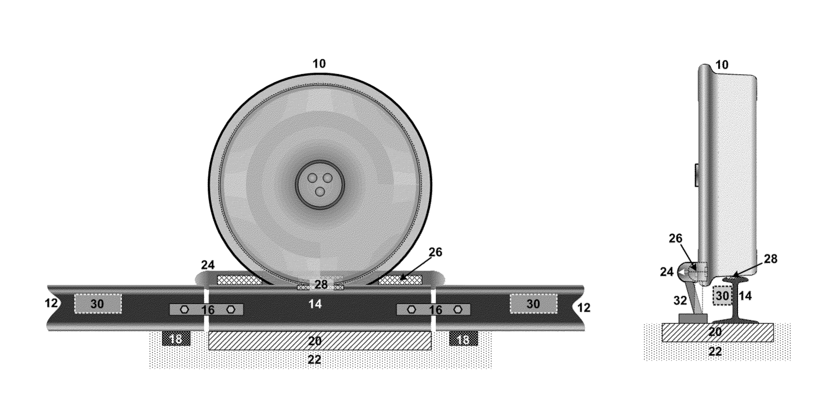
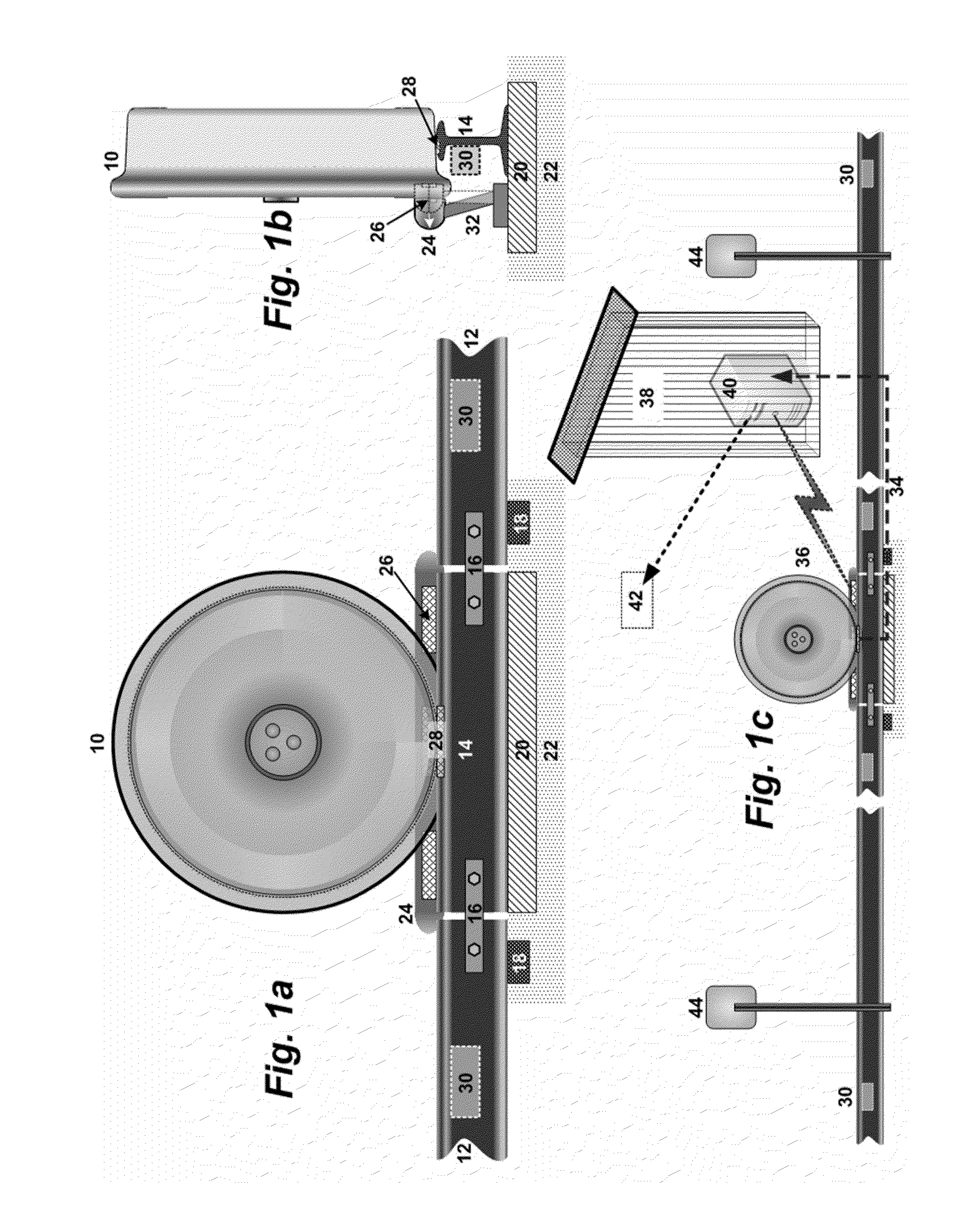
[0038]FIGS. 1a-1c depict views of an illustrative device and system according to an embodiment with two variations. As seen in FIG. 1a, railroad wheel 10 is traveling down a set of rails 12, and travels over an isolated rail segment 14. Isolated segment 14 is connected to the remaining rails 12 by connecting devices 16 which prevent the rail segment 14 from moving with respect to rails 12 without strongly coupling the segment 14 and the rails 12. An illustrative connecting device 16 comprises joint bars (sometimes referred to as “fishplates”), which can be made from a glass-reinforced epoxy laminate, such as G-10, or a similar composite having high strength and internal damping. The connecting device 16 isolates rail segment 14 from the vibrations caused by other wheels 10 in front of and behind the current wheel 10. Furthermore, while rails 12 are supported by standard ties 18, the rail segment 14 can be mounted on a vibration absorbing or isolating structure 20, e.g., embedded in ...


PUM

PropertyMeasurementUnit
timeaaaaaaaaaa
lengthaaaaaaaaaa
lengthaaaaaaaaaa

Abstract

A solution for evaluating the condition of a rail component based on resonant response profiles across a set of bands of vibrations. The vibrations can be induced into the target component during normal operation of the target component. The resonant response profile of the rail component can vary depending on wear or damage, and thus can be used to determine whether the rail component can safely remain in use. An embodiment comprises an isolated segment of rail of a length selected to allow a single railroad wheel on it at a time, with a set of devices which can induce specific vibrations into the wheel as it passes, and another set of devices which can acquire the resonance signals from the wheel.

Description

REFERENCE TO PRIOR APPLICATIONS[0001]The current application claims the benefit of U.S. Provisional Application No. 61 / 688,842, titled “Ultrasonic analysis-based inspection system and method for rail components”, which was filed on 23 May 2012, and which is hereby incorporated by reference.TECHNICAL FIELD[0002]The disclosure relates generally to nondestructive inspection of vehicle components, and specifically to a new and innovative solution for evaluating a condition of railroad wheels and / or other components of a rail transportation system.BACKGROUND ART[0003]Evaluation of the resonance of an object to various acoustic input frequencies has been known as a method for determining the condition of metallic or otherwise highly rigid objects or components for centuries. In fact, some uses of this principle may pre-date the industrial revolution. With respect to rail, early British railroad engineers would tap the wheels of a train and use the sound to determine if a crack was present...

Claims


Application Information

Patent Timeline
Patent Type & Authority Patents(United States)
IPC IPC(8): G01N29/12G01N29/44
CPCG01N29/12G01N29/4427G01N2291/2696G01M17/10G01N29/4409G01N29/46G01N2291/023
Inventor MIAN, ZAHID F.JOHNSON, WILLIAM B.
Owner INT ELECTRONICS MACHINES
Why Eureka
Try Eureka