Eureka AIR delivers breakthrough ideas for toughest innovation challenges, trusted by R&D personnel around the world.

Enhanced braided sleeve and method of construction thereof

a technology of sleeve and braid, which is applied in the direction of braid, ornamental textile articles, transportation and packaging, etc., can solve the problems of reducing the service life of the sleeve,

Active Publication Date: 2016-07-19
FEDERAL MOGUL POWERTAIN LLC
View PDF32 Cites 3 Cited by
  • Summary
  • Abstract
  • Description
  • Claims
  • Application Information

AI Technical Summary

Benefits of technology

[0006]In accordance with another aspect of the invention, the braided protective sleeve further includes a plurality of inserted yarns interlaced with the braided yarns, wherein the inserted yarns extend substantially parallel to the longitudinal axis. The inserted yarns further enhance the ability to provide the sleeve with the performance characteristics sought for the intended application.
[0007]In accordance with another aspect of the invention, the inserted yarns can be interlaced so that they are exposed to the internal cavity to provide enhanced protection to contents therein and / or an enhanced locating feature therein for attachment to the contents therein, wherein the inserted yarns are substantially concealed from the surrounding environment by the outer surface such that the inserted yarns are protected against damage.
[0008]In accordance with another aspect of the invention, the inserted yarns can be interlaced so that they are exposed to the surrounding environment to provide enhanced protection against abrasion and / or an enhanced locating feature for attachment to an external surface, wherein the inserted yarns can be substantially concealed from the internal cavity to avoid unwanted contact with the contents therein.
[0014]In accordance with yet another aspect of the invention, the method can further include exposing the interlaced yarns to the internal cavity and substantially concealing the interlaced yarns from exposure to the surrounding environment.
[0015]In accordance with yet another aspect of the invention, the method can further include exposing the interlaced yarns to the surrounding environment and substantially concealing the interlaced yarns from exposure to the internal cavity.
[0016]In accordance with yet another aspect of the invention, the method can further include exposing at least some of the interlaced yarns to the internal cavity and substantially concealing these yarns from exposure to the surrounding environment and exposing at least some of the interlaced yarns to the surrounding environment and substantially concealing these yarns from exposure to the internal cavity.

Problems solved by technology

Although woven and knitted sleeves can be useful for the their intended use, in some applications, they may prove less than optimal, including, from a functional standpoint, for example, if woven, the sleeves may be too stiff, radially inflexible or radially inelastic, and if knitted, the sleeves may be too radially elastic and bulky.
Further, from a manufacturing standpoint, both woven and knit sleeves are generally costly.

Method used


Image

  • Enhanced braided sleeve and method of construction thereof
  • Enhanced braided sleeve and method of construction thereof
  • Enhanced braided sleeve and method of construction thereof

Examples


Embodiment Construction

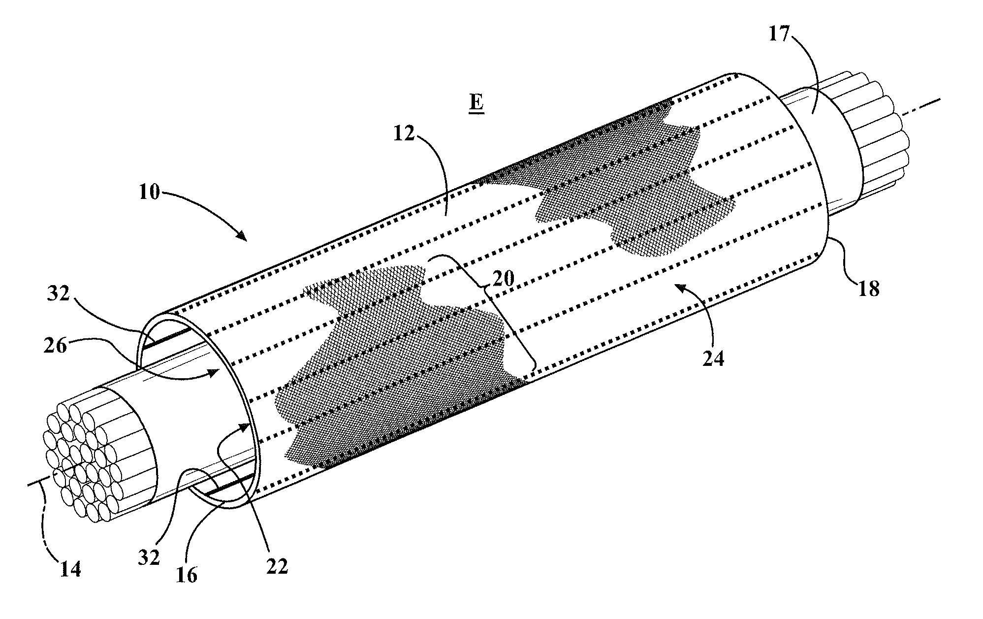
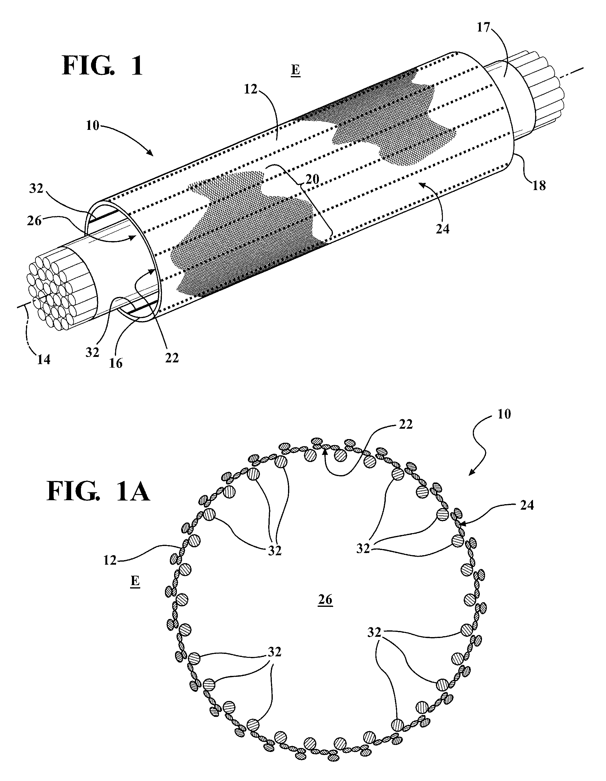
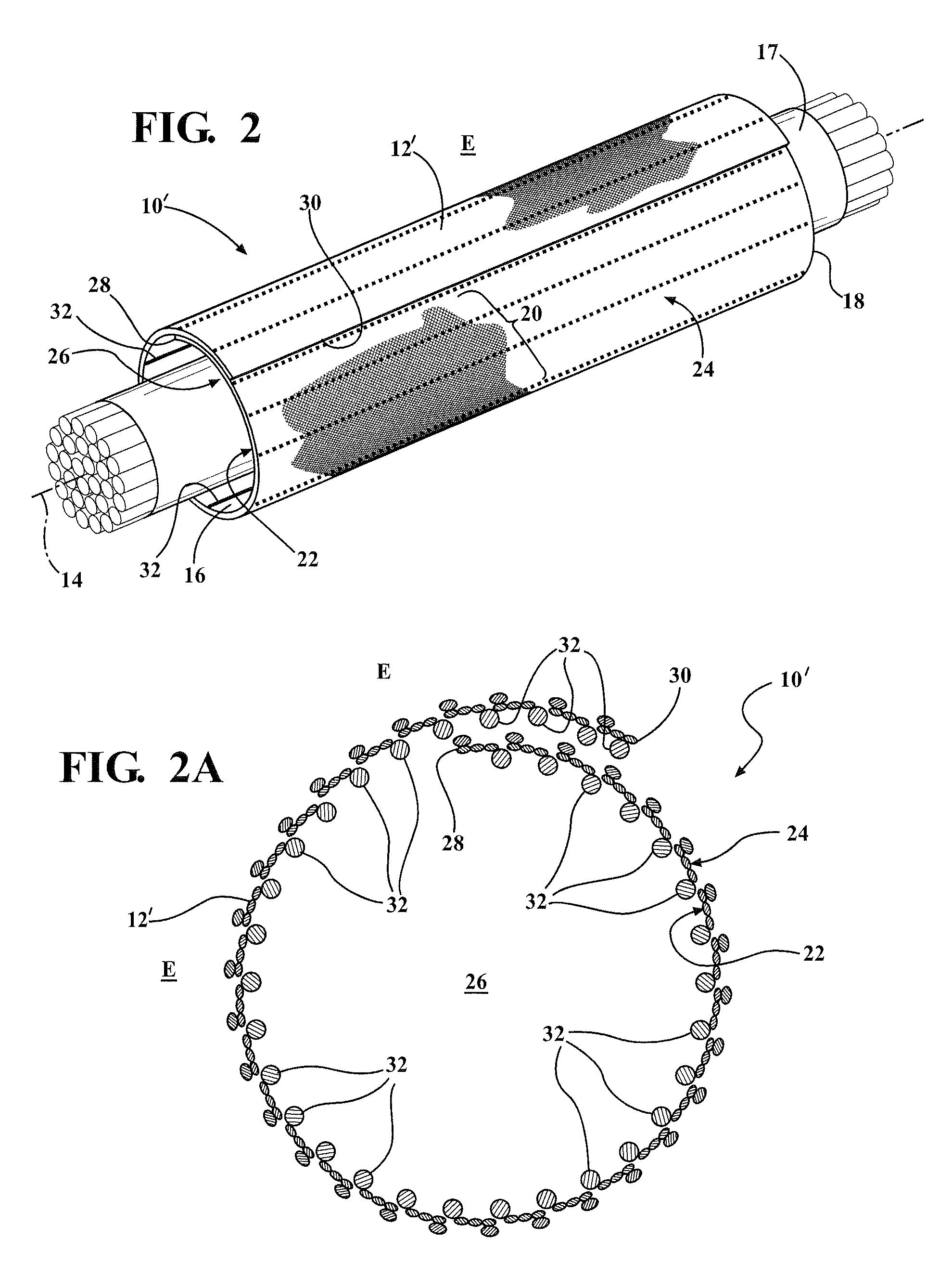
[0043]Referring in more detail to the drawings, FIGS. 1 and 2 illustrate protective braided textile sleeves, identified respectively by reference numerals 10 and 10′, constructed in accordance with certain aspects of the invention. The sleeves 10, 10′ have similar braid patterns, however, the sleeve 10 has a circumferentially continuous, seamless wall 12 (FIG. 1A), while the sleeve 10′ has a wrappable wall 12′ (FIG. 2A), with any other notable differences being discussed hereafter. For simplicity, unless otherwise detailed, the same reference numerals are used hereafter to designate like features. The walls 12, 12′ extend along a central longitudinal axis 14 between opposite ends 16, 18. The walls 12, 12′ are formed via a plurality of braided yarns 20 to provide inner and outer surfaces 22, 24 of the sleeve 10. The inner surface 22 bounds an internal cavity 26 sized for receipt of an elongate member 17 therein, such as a pipe or wire harness, for example, and the outer surface 24 is...


PUM

PropertyMeasurementUnit
temperatureaaaaaaaaaa
impact forcesaaaaaaaaaa
abrasion resistanceaaaaaaaaaa

Abstract

A braided protective sleeve and method of construction thereof is provided. The sleeve has a wall extending along a longitudinal axis of the sleeve. The wall includes a plurality of braided yarns forming inner and outer surfaces of the sleeve. The inner surface bounds an internal cavity and the outer surface is exposed to the surrounding environment. The yarns are braided with one another in a X / Y braid pattern with X and Y being different numerical values from one another. The numerical values of X and Y can be selected as desired to provide the sleeve with the enhanced physical performance characteristics desired. A plurality of yarns extending substantially parallel to the longitudinal axis can be interlaced with the braided yarns. The interlaced yarns can be exposed to the internal cavity and concealed from the environment; exposed to the environment and concealed from the internal cavity, or both.

Description

BACKGROUND OF THE INVENTION[0001]1. Technical Field[0002]This invention relates generally to textile sleeves for protecting elongate members, and more particularly to braided textile sleeves and to their method of construction.[0003]2. Related Art[0004]In applications requiring protection against abrasion and impact forces to elongate members, such as wire harnesses or tubular members, it is known to surround the elongate member with a multi-faced woven or knitted textile sleeve. For example, if woven, the fill yarn can be provided as a first yarn type to form an inner face of the sleeve, while the warp yarn can be provided as a second type of yarn, different from the first type of yarn, to form an outer face of the sleeve. As such, the first and second yarns can be selected from the type of material best suited to provide the protection desired. Likewise, if knitted, different types of yarn can be knitted together to form respective inner and outer faces having different properties...

Claims


Application Information

Patent Timeline
Patent Type & Authority Patents(United States)
IPC IPC(8): D04C1/06F16L57/06
CPCD04C1/06F16L57/06D10B2403/02411Y10T428/13Y10T428/1362D10B2403/0311D10B2505/12D10B2401/041
Inventor GAO, TIANQIMALLOY, CASSIE M.HARRIS, DAVID A.PIOTROWSKI, MICHAELKRAUSER, LEIGH
Owner FEDERAL MOGUL POWERTAIN LLC
Why Eureka
Eureka Blog
Learn More