Panoramic multi-scale imager and method therefor

a multi-scale, imager technology, applied in the field of panoramic imaging systems, can solve the problems of limited success of prior-art approaches

Active Publication Date: 2016-07-19
APPLIED QUANTUM TECH +1
View PDF58 Cites 7 Cited by
  • Summary
  • Abstract
  • Description
  • Claims
  • Application Information

AI Technical Summary

Benefits of technology

[0021]The secondary lens and focal plane array of each camera defines a first optical axis. Further, each camera defines a second axis that extends normally from the surface of the objective lens to the center of its respective secondary lens. In some embodiments, the first axis of each camera is non-co-linear with its respective second axis. As a result, an image that is highly oblique to the second axis is nearly on-axis for the first axis. This enables each camera to correct residual aberrations more easily, since rays aligned with the optical axis of an optical system normally experience fewer aberrations than rays that are highly oblique to that optical axis. In some embodiments, each secondary lens includes a first surface that is not symmetric about the first axis of its respective camera. This enables the secondary lens to refract rays incident on the secondary lens from the direction of the objective lens so that the rays align with the first axis of the camera.
[0023]An embodiment of the present invention is a panoramic imaging system comprising: a first mirror, the first mirror directing light from a scene to an objective lens; the objective lens, the objective lens forming an image based on the light at a first image field, wherein the objective lens is dimensioned and arranged to reduce the magnitude of a first aberration introduced on the light by the first mirror; and a plurality of cameras that segment the image into a plurality of image portions, wherein each of the plurality of cameras includes a secondary lens and a focal plane array having a plurality of detector pixels, each secondary lens being operative for (1) forming a sub-image based on the respective image portion of the camera, the sub-image being formed on a region of the focal plane array that includes at least two detector pixels, and (2) further reducing the magnitude of the first aberration.

Problems solved by technology

Such prior-art approaches have had limited success, however, due to problems associated with mapping the panoramic images onto planar sensing region and efficiency with which the scene is captured.

Method used


Image

  • Panoramic multi-scale imager and method therefor
  • Panoramic multi-scale imager and method therefor
  • Panoramic multi-scale imager and method therefor

Examples


Embodiment Construction

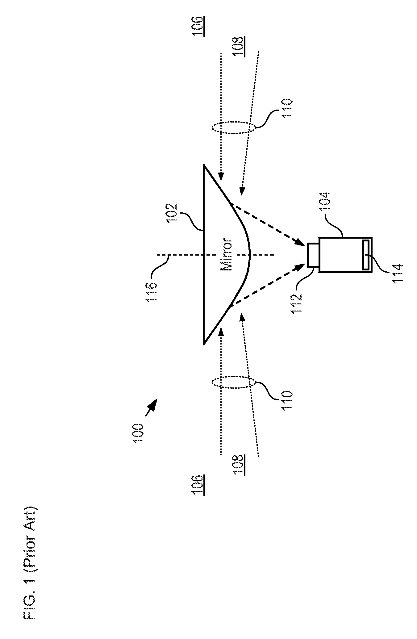
[0034]FIG. 1 depicts a schematic drawing of a side view of a panoramic imaging system in accordance with the prior art. Imager 100 comprises mirror 102 and camera 104. Imager 100 forms an image of panorama 108, which is a portion of scene 106. Panorama 108 extends 360° around the imager. Imager 100 is representative of panoramic imaging systems described in U.S. Pat. No. 7,123,777, which is incorporated herein by reference.

[0035]Mirror 102 is a convex reflective mirror having a substantially symmetric shape about axis of rotation 116. Examples of such mirrors include hyperboloidal mirrors, spherical mirrors, and parabolic mirrors. Mirror 102 receives light rays 110 from scene 106 and reflects them to camera 104.

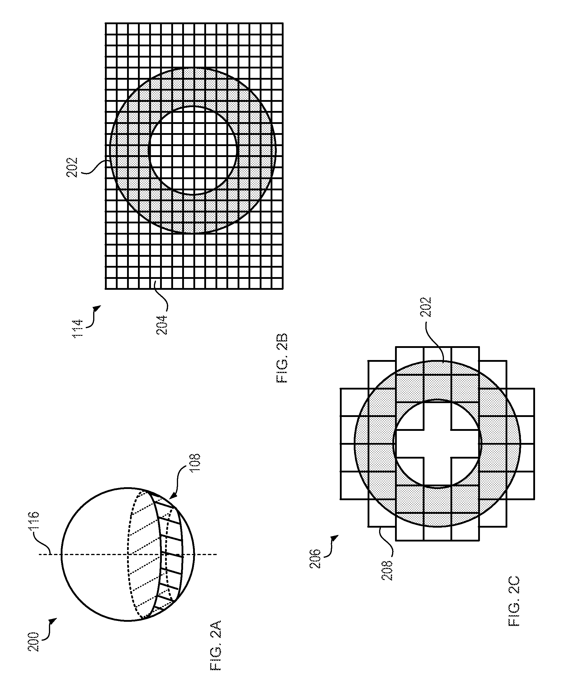
[0036]Light rays 110 are received from mirror 102 at input lens 112, which forms an image on the surface of focal plane array 114.

[0037]Focal plane array 114 is a rectangular array of detector pixels, typically CCD elements. Each detector pixel converts its received light int...


PUM


Abstract

A panoramic imager comprising a mirror and a multi-scale imaging system is presented. The multi-scale imaging system comprises an objective lens and a plurality of cameras that is arranged in a non-planar arrangement at the image field of the objective lens. The objective lens reduces a first aberration introduced by the mirror, and each camera further reduces any residual first aberration. As a result, panoramic imagers of the present invention can provide improved image quality and higher resolution than panoramic imagers of the prior art.

Description

CROSS REFERENCE TO RELATED APPLICATIONS[0001]This case is a continuation-in-part of co-pending U.S. patent application Ser. No. 13 / 095,407, filed Apr. 27, 2011, entitled “Monocentric Lens-based Multi-scale Optical Systems and Methods for Use”, which claims the benefit of U.S. Provisional Patent Application Ser. No. 61 / 328,213, filed Apr. 27, 2010, and which is a continuation-in-part of U.S. patent application Ser. No. 12 / 651,894 (now U.S. Pat. No. 8,259,212), filed Jan. 4, 2010, entitled “Multiscale Optical System”, which claims priority to U.S. Provisional Patent Application Ser. No. 61 / 142,499, filed Jan. 5, 2009, each of which is incorporated by reference herein.[0002]If there are any contradictions or inconsistencies in language between this application and one or more of the cases that have been incorporated by reference that might affect the interpretation of the claims in this case, the claims in this case should be interpreted to be consistent with the language in this case....

Claims


Application Information

Patent Timeline
Patent Type & Authority Patents(United States)
IPC IPC(8): G03B37/00G02B13/06H04N5/232H04N5/225
CPCG03B37/00G02B13/06H04N5/2251H04N5/23238H04N23/55H04N23/60H04N23/698
Inventor MCCAIN, SCOTT THOMASBRADY, DAVID JONESMARKS, DANIEL
Owner APPLIED QUANTUM TECH
Why Eureka
Try Eureka