Liquid container

a liquid container and liquid technology, applied in packaging, printing, etc., can solve the problems of inability to meet the needs of liquid supply, so as to achieve enhanced strength of end portions, suppress leakage of liquid via liquid supply ports, and enhance the arrangement position of liquid cartridges by end portions

Active Publication Date: 2016-07-26
SEIKO EPSON CORP
View PDF8 Cites 53 Cited by
  • Summary
  • Abstract
  • Description
  • Claims
  • Application Information

AI Technical Summary

Benefits of technology

[0010][2] In the liquid container in the above mode, the end portion of the housing member may be housed in a space formed within the projecting portion. With the liquid container in this mode, since the end portion of the housing member is housed in the inside space of the projecting portion, a change of the arrangement position and the arrangement angle of the liquid cartridge within the exterior member is further suppressed. Furthermore, the efficiency of usage of the space within the exterior member is enhanced, and the size and the weight of the liquid container can be reduced.
[0013][5] In the liquid container in the above mode, the housing member may have a bent portion that is bent between the wall portion and the liquid cartridge. With the liquid container in this mode, a change of the arrangement position and the arrangement angle of the liquid cartridge within the exterior member is further suppressed by the bent portion. Furthermore, since the bent portion functions as an impact absorbing portion, the characteristic of protection of the liquid cartridge is enhanced.
[0028][20] In the liquid container in the above mode, the liquid cartridge may be equipped with a cover member that covers the liquid supply port. With the liquid container in this mode, leakage of liquid via the liquid supply port is suppressed.
[0029][21] In the liquid container in the above mode, the end portion may be an adhered portion formed by adhering end portions of the sheet-shaped member to each other. With the liquid container in this mode, since the strength of the end portions is enhanced, a function of restricting the arrangement angle and the arrangement position of the liquid cartridge by the end portion is enhanced.

Problems solved by technology

If unexpected impact is applied to an ink cartridge during distribution, for example, there is a possibility that ink leaks from an opening portion such as an atmosphere introduction hole, depending on the angle of arrangement thereof.
In addition, in the case of an ink cartridge containing pigment ink, there is a possibility that an uneven concentration distribution of a color material component occurs in the ink when the ink cartridge is left standing at a certain arrangement angle for a long time.
Depending on the condition of the concentration distribution of the color material component, print quality degrades in some cases, e.g., the concentration of a printed image becomes uneven.
However, with the technique in JP-A-2003-034362, there is a possibility that the arrangement posture of the ink cartridge is not different from the arrangement posture at the time of installation in the printer depending on the arrangement angle of the package itself.
With the liquid container in this mode, since the arrangement posture is unstable when the liquid container is arranged at an arrangement angle at which the atmosphere introduction hole is oriented vertically downward, the arrangement at this arrangement angle is restricted.
With the liquid container in this mode, the arrangement posture is unstable when the liquid container is arranged at an arrangement angle at which the atmosphere introduction hole is oriented vertically downward, and the arrangement at this arrangement angle is restricted.
With the liquid container in this mode, since the arrangement posture is unstable when the liquid container is arranged at an arrangement angle at which the atmosphere introduction hole is oriented vertically downward, the arrangement at this arrangement angle is restricted.

Method used


Image

  • Liquid container
  • Liquid container
  • Liquid container

Examples


first embodiment

[0062]A. First Embodiment

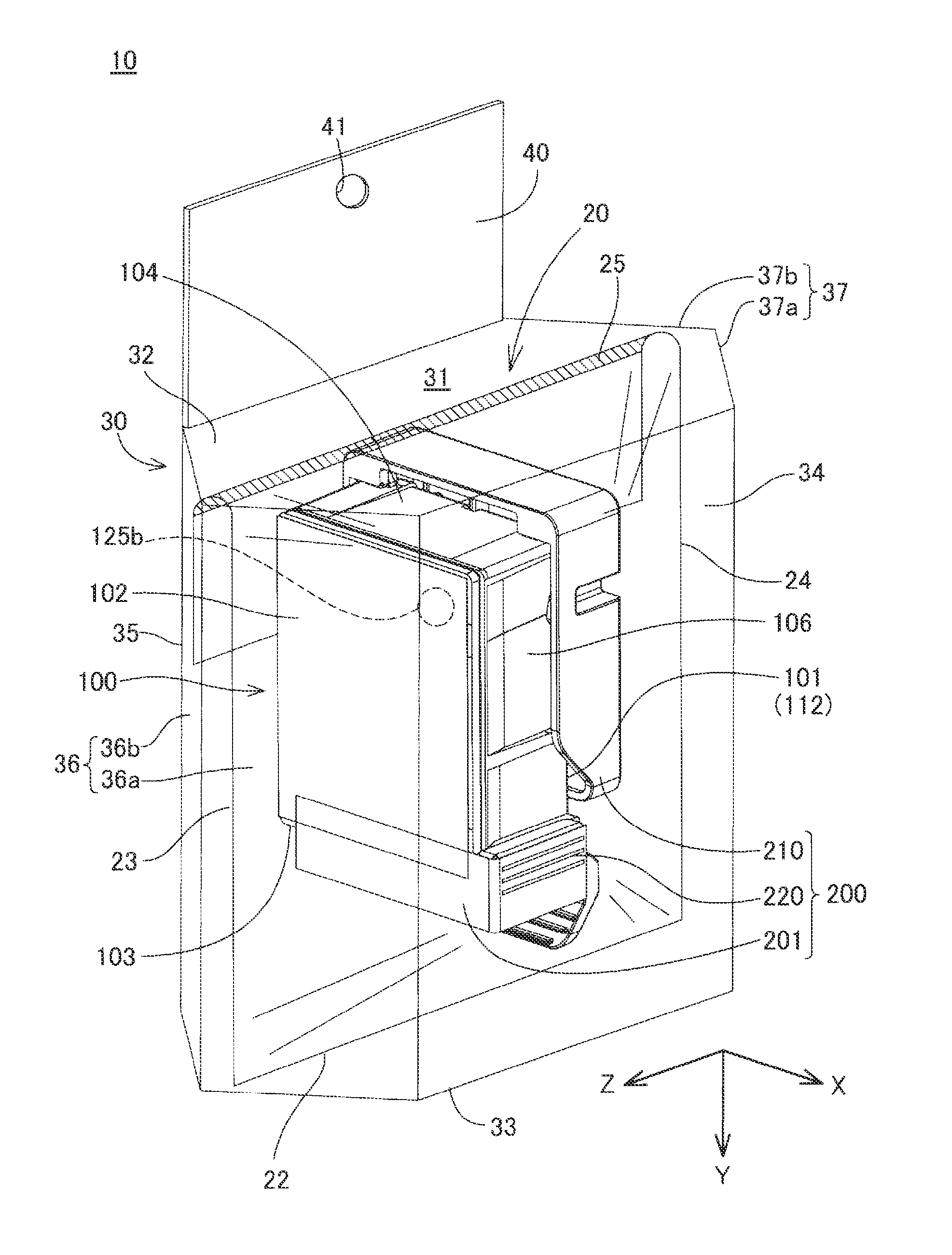
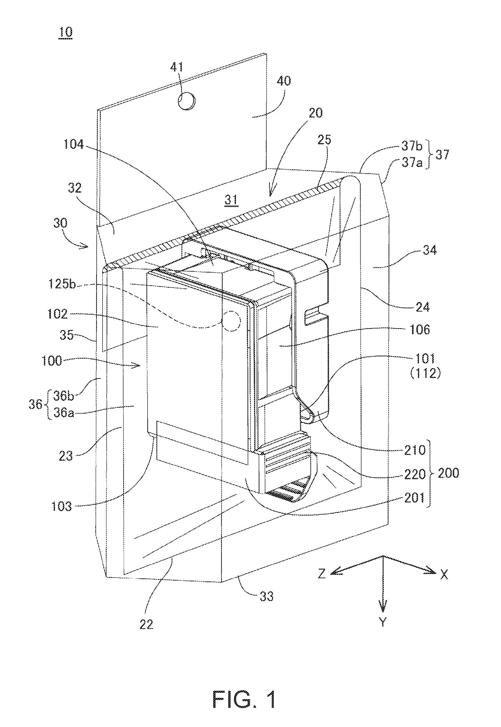
[0063]FIG. 1 is a schematic perspective view showing a configuration of a packaging body 10 of an ink cartridge (hereinafter also referred to simply as a “cartridge”), which serves as a first embodiment of the invention. In FIG. 1, for the sake of convenience, a bag-shaped member 20 and a box-shaped member 30 are shown in a state where the inside thereof is visible. In FIG. 1, arrows X, Y, and Z indicating three directions orthogonal to one another with the cartridge 100 as a reference are shown. The arrows X, Y, and Z correspond to arrows X, Y, and Z, respectively, shown in the drawings used in the later description. The directions indicated by the arrows X, Y, and Z will be described later.

[0064]The packaging body 10 is a mode of a liquid container, and the cartridge 100 is packaged therein for the purpose of commercial distribution or the like. The packaging body 10 has a configuration in which an unused cartridge 100 is housed in the bag-shaped member 20...

second embodiment

[0130][B. Second Embodiment]

[0131]FIG. 10 is a schematic view of a packaging body 10A, which serves as a second embodiment of the invention, as viewed in a direction extending from the upper face wall portion 32 toward the bottom face wall portion 33 of the box-shaped member 30. In FIG. 10, as in FIG. 9, the packaging body 10A is shown in a state of being arranged with the first outer wall surface 36a of the first side wall portion 36 of a box-shaped member 30A as a bottom face. The packaging body 10A in the second embodiment is roughly the same as the packaging body 10 in the first embodiment except that the configuration of the box-shaped member 30A has been changed such that the position of the center of gravity PG when the packaging body 10A is arranged with the outer wall surface 36a, 36b, 37a, or 37b of the first side wall portion 36 or the second side wall portion 37 as a bottom face is different.

[0132]When the packaging body 10A in the second embodiment is arranged with the ...

third embodiment

[0133][C. Third Embodiment]

[0134]FIGS. 11 and 12 are schematic views for illustrating a configuration of a packaging body 10B in a third embodiment. FIG. 11 shows a bag-shaped member 20B in the third embodiment in a state of housing the cartridge 100. FIG. 12 shows the packaging body 10B in the third embodiment as viewed in a direction extending from the upper face wall portion 32 toward the bottom face wall portion 33 of the box-shaped member 30. In FIG. 12, for the sake of convenience, the cartridge 100 and the bag-shaped member 20B housed in the box-shaped member 30 are indicated by broken lines. The packaging body 10B in the third embodiment has roughly the same configuration as that of the packaging body 10 in the first embodiment except that the configuration of the bag-shaped member 20B is different, and that the housing state of the box-shaped member 30 is different in a manner described below.

[0135]In the bag-shaped member 20B in the third embodiment, the sealed portion 25 ...


PUM

PropertyMeasurementUnit
gravityaaaaaaaaaa
angleaaaaaaaaaa
concentrationaaaaaaaaaa

Abstract

A technique that can restrict an arrangement angle of a liquid cartridge before use in a packaged state is provided. A packaging body 10 of a cartridge 100 includes a bag-shaped member 20 and a box-shaped member 30. The bag-shaped member 20 houses the cartridge 100. The box-shaped member 30 houses the cartridge 100 housed in the bag-shaped member 20. The cartridge 100 has an atmosphere introduction hole 125b capable of introducing the atmosphere to the inside, and the box-shaped member 30 has a first side wall portion 36 located at a position opposed to the atmosphere introduction hole 125b. The first side wall portion 36 has a first and second outer wall surfaces 36a and 36b that intersect each other to constitute a projecting portion that projects outward. A third end side portion 23 of the bag-shaped member 20 is housed at a corner portion between the first and second outer wall surfaces 36a and 36b.

Description

CROSS-REFERENCE TO RELATED APPLICATIONS[0001]This application claims priority to Japanese Patent Application No. 2014-146450 filed on Jul. 17, 2014. The entire disclosure of Japanese Patent Application No. 2014-146450 is incorporated herein by reference.BACKGROUND[0002]1. Technical Field[0003]The present invention relates to liquid containers.[0004]2. Related Art[0005]Hitherto, an ink cartridge is used to supply ink to an inkjet printer (hereinafter also referred to simply as a “printer”). An ink cartridge is housed in a packaging member such as a paper box when being commercially distributed, for example (e.g., JP-A-2003-034362).[0006]If unexpected impact is applied to an ink cartridge during distribution, for example, there is a possibility that ink leaks from an opening portion such as an atmosphere introduction hole, depending on the angle of arrangement thereof. In addition, in the case of an ink cartridge containing pigment ink, there is a possibility that an uneven concentrat...

Claims


Application Information

Patent Timeline
Patent Type & Authority Patents(United States)
IPC IPC(8): B41J2/175B65D75/36
CPCB41J2/17553B41J2/17533B65D75/36B41J2/17513B41J2/1752B41J2/1753
Inventor MIZUTANI, TADAHIROOKAZAWA, NORIAKIKOBAYASHI, HIROYUKI
Owner SEIKO EPSON CORP
Why Eureka
Try Eureka