Laser processing enabling radio frequency identification (RFID) customization
What is AI technical title?
AI technical title is built by Patsnap AI team. It summarizes the technical point description of the patent document.
a laser processing and radio frequency identification technology, applied in the field of electronic article surveillance (eas), radio frequency (rf) and/or rf identification (rfid) tags and devices, can solve the problems of high degree of customization of otp fuse, limited programming requirements, and high cost of mask encoding for this type of customization, etc., to achieve low cost and high throughput approach
Active Publication Date: 2016-07-26
ENSURGE MICROPOWER ASA
View PDF9 Cites 0 Cited by
Summary
Abstract
Description
Claims
Application Information
AI Technical Summary
This helps you quickly interpret patents by identifying the three key elements:
Problems solved by technology
Method used
Benefits of technology
Benefits of technology
[0016]Embodiments of the present invention can advantageously provide a relatively low cost and high throughput approach for customized RFID devices. Further, embodiments of the present invention can advantageously be implemented using laser patterning technology. These and other advantages of the present invention will become readily apparent from the detailed description of preferred embodiments below.
Problems solved by technology
However, for RFID applications, the relatively large number of unique IDs needed makes mask encoding for this type of customization prohibitively expensive.
OTP fuses offer a high degree of customization, but are limited by the programming requirements.
For example, laser programming by blowing select fuses may be limited by the applied laser power, which depends on the line width of the fuse.
For thin film transistor (TFT) designs with line widths larger than 2 μm, the power required may be so high that the throughput of conventional laser fuse tools may not be cost effective for RFID devices.
Similarly, the limited power available in certain RF applications may restrict the ability to blow select fuses by passing a high current through them.
EEPROM elements are relatively easy to program, but conventional EEPROM elements may have manufacturing process challenges and / or costs that make them a less-than-optimal solution for RFID applications.
Method used
Image
Click on the blue label to locate the original text in one second.
Reading with bidirectional positioning of images and text.
Examples
Embodiment Construction
[0037]Reference will now be made in detail to the preferred embodiments of the invention, examples of which are illustrated in the accompanying drawings. While the invention will be described in conjunction with the preferred embodiments, it will be understood that they are not intended to limit the invention to these embodiments. On the contrary, the invention is intended to cover alternatives, modifications and equivalents that may be included within the spirit and scope of the invention as defined by the appended claims. Furthermore, in the following detailed description of the present invention, numerous specific details are set forth in order to provide a thorough understanding of the present invention. However, it will be readily apparent to one skilled in the art that the present invention may be practiced without these specific details. In other instances, well-known methods, procedures, components, and circuits have not been described in detail so as not to unnecessarily ob...
PUM
Property
Measurement
Unit
width
aaaaa
aaaaa
length
aaaaa
aaaaa
area
aaaaa
aaaaa
Abstract
Methods, algorithms, processes, circuits, and / or structures for laser patterning suitable for customized RFID designs are disclosed. In one embodiment, a method of laser patterning of an identification device can include the steps of: (i) depositing a patternable resist formulation on a substrate having configurable elements and / or materials thereon; (ii) irradiating the resist formulation with a laser tool sufficiently to change the solubility characteristics of the resist in a developer; and (iii) developing exposed areas of the resist using the developer. Embodiments of the present invention can advantageously provide a relatively low cost and high throughput approach for customized RFID devices.
Description
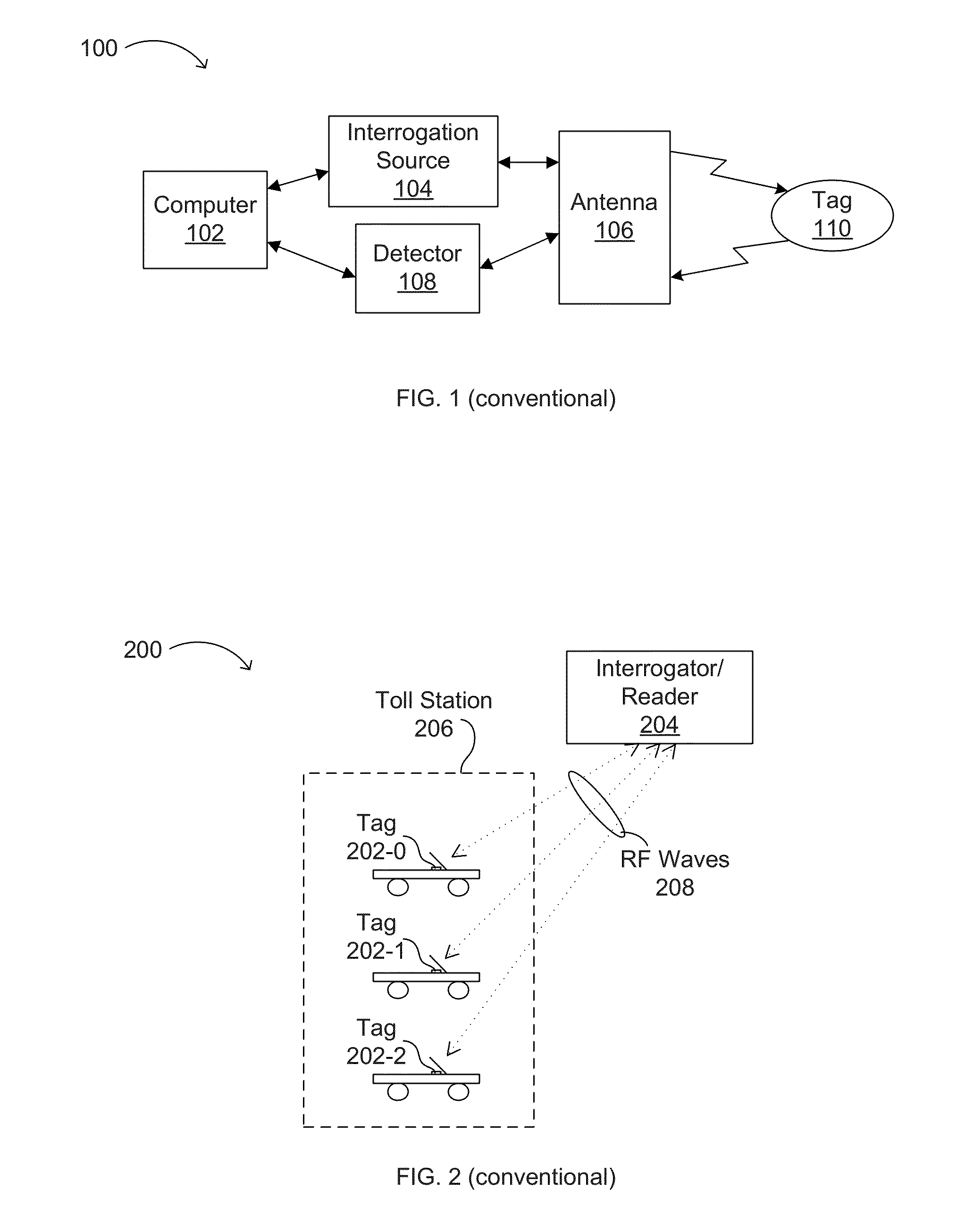
RELATED APPLICATIONS[0001]This application is a divisional of U.S. patent application Ser. No. 11 / 595,839, filed Nov. 8, 2006, which claims the benefit of U.S. Provisional Application No. 60 / 748,974, filed Dec. 7, 2005, each of which are incorporated herein by reference in their entireties.FIELD OF THE INVENTION[0002]The present invention generally relates to the field of electronic article surveillance (EAS), radio frequency (RF) and / or RF identification (RFID) tags and devices. More specifically, embodiments of the present invention pertain to EAS, RF and / or RFID structures and methods of manufacture, production, and / or customization.DISCUSSION OF THE BACKGROUND[0003]Low cost RFID systems, typically including an interrogator or “reader” and an electronic label or “tag,” are desirable in a variety of applications, such as retail, supply chain management, logistics, library management, anti-counterfeiting, access control, and baggage claim systems, as just a few examples. Other emer...
Claims
Application Information
Patent Timeline
Application Date:The date an application was filed.
Publication Date:The date a patent or application was officially published.
First Publication Date:The earliest publication date of a patent with the same application number.
Issue Date:Publication date of the patent grant document.
PCT Entry Date:The Entry date of PCT National Phase.
Estimated Expiry Date:The statutory expiry date of a patent right according to the Patent Law, and it is the longest term of protection that the patent right can achieve without the termination of the patent right due to other reasons(Term extension factor has been taken into account ).
Invalid Date:Actual expiry date is based on effective date or publication date of legal transaction data of invalid patent.

