Device for fixing an electrical connection terminal to a support

a technology for fixing devices and electrical connections, which is applied in the direction of coupling device connections, coupling device engagement/disengagement, screws, etc., can solve the problems of increasing the number of pieces forming the fixing device, loosening the screw holding the terminal, and not being traditionally used for fixing devices. to prevent accidental loosening of screws

Active Publication Date: 2016-07-26
DUBUIS & CIE
View PDF52 Cites 3 Cited by
  • Summary
  • Abstract
  • Description
  • Claims
  • Application Information

AI Technical Summary

Benefits of technology

[0019]The locking portion thus makes it possible to prevent accidental loosening of the screw under the effect of vibrations which are imparted to the support or rotation of the terminal relative to the support.

Problems solved by technology

However, a fixing device of this type is not traditionally used in applications which require resistance to vibrations, such as for earthing equipment on board an aircraft.
This is because the vibrations to which the equipment is subjected can cause loosening of the screw which holds the terminal.
In any case, adding such a washer would result in an increase in the number of pieces forming the fixing device and in an increase in the weight of the fixing device which is unacceptable for the intended applications, said device being multiplied a large number of times in an aircraft.

Method used


Image

  • Device for fixing an electrical connection terminal to a support
  • Device for fixing an electrical connection terminal to a support
  • Device for fixing an electrical connection terminal to a support

Examples


first embodiment

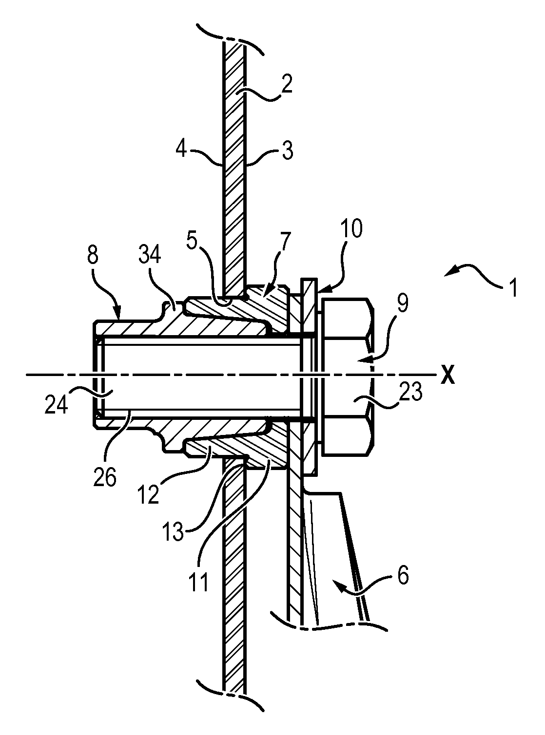
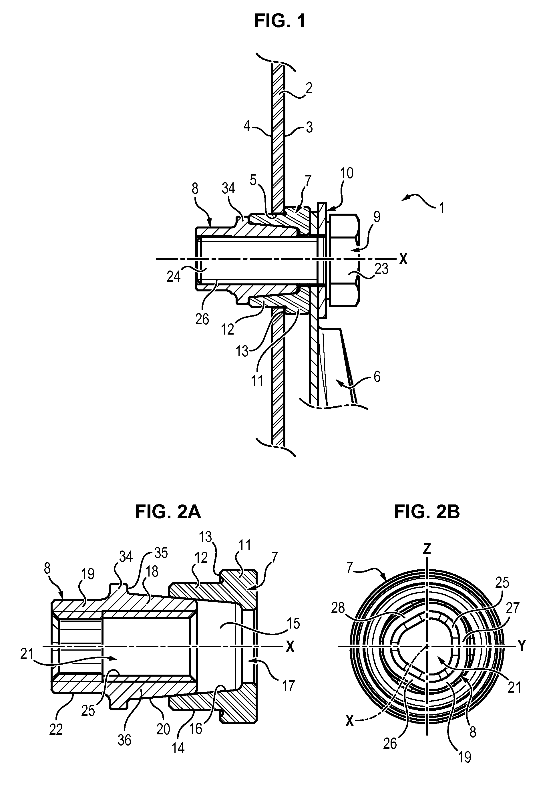
[0051]FIGS. 2A and 2B are schematic views of a ring 7 and dowel 8 assembly according to the invention, the assembly being shown before mounting on the support 2.

[0052]The ring 7 is made of metal, preferably of aluminium alloy or copper. The ring 7 has a first portion 11 (or collar) which is suitable for being placed in electrical contact with the terminal 6, and a second portion 12 which is suitable for being inserted in the hole 5 through the wall 2. The ring 7 comprises a shoulder 13 connecting the first portion 11 and the second portion 12, the shoulder 13 being suitable for being supported against a surface of the wall 2, on the first side 3 of the wall 2 when the ring 7 is positioned in the hole 5.

[0053]The first portion 11 of the ring 7 has a hole 17 which makes it possible to insert the screw 9 through the ring 7, from the first side 3 of the wall 2 when the ring 7 is positioned in the hole 5.

[0054]The second portion 12 has an outer surface 14 which is suitable for being in c...

second embodiment

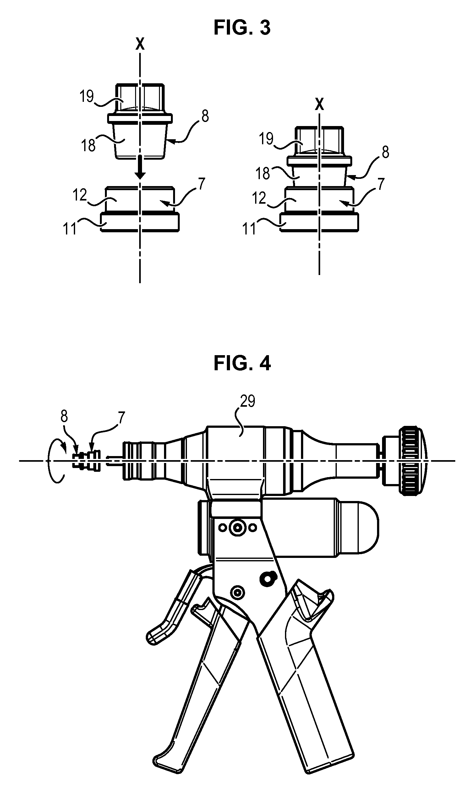
[0083]FIGS. 7A and 7B are schematic views of a ring 7 and dowel 8 assembly according to the invention.

[0084]This second embodiment is the same as the first embodiment except for the fact that the second portion 19 of the dowel 8 has been radially deformed in two diametrically opposite regions 37, 38. In this case, the dowel 8 has an oblong-shaped or bilobal cross section in the locking portion 19.

[0085]Due to this distortion, the internal thread 25 is suitable for generating, in the regions 37, 38, a frictional force on the external thread 26 of the screw 9 when the screw 9 is screwed into the dowel 8.

third embodiment

[0086]FIGS. 8A and 8B are schematic views of a ring 7 and dowel 8 assembly according to the invention.

[0087]This third embodiment is the same as the first embodiment except for the fact that the second portion 19 of the dowel 8 has been radially deformed in four regions 39 to 42 which are arranged in pairs symmetrically on either side of a plane of symmetry Z which passes through the axis X of the bore. In this case, the dowel 8 has a quadrilobal cross section in the locking portion 19.

[0088]Due to this distortion, the internal thread 25 is suitable for generating, in the regions 39 to 42, a frictional force on the external thread 26 of the screw 9 when the screw 9 is screwed into the dowel 8.


PUM

PropertyMeasurementUnit
diameteraaaaaaaaaa
internal radiusaaaaaaaaaa
thicknessaaaaaaaaaa

Abstract

A fixing device for fixing an electrical connection terminal to a support having a first side, a second side opposite to the first side, and defining a through hole of a first diameter. The fixing device comprises: a ring including a receiving portion partially defining an axial recess and insertable in the through hole; a dowel including an insert portion axially insertable into the recess of the ring and a locking portion axially spaced from the insert portion, the dowel partially defining an axial bore including an internal thread, and in the locking portion the internal thread of the bore is a distorted locking thread; and a fixing screw including a threaded shank engagable with the dowel. Tightening of the fixing screw draws the insert portion of the dowel axially into the recess of the ring, thereby radially expanding the ring into press-fit engagement with the through hole.

Description

CROSS-REFERENCE TO RELATED APPLICATIONS[0001]This application is a continuation of PCT Application No. PCT / EP2013 / 072829, filed on Oct. 31, 2013 which claims priority from French Patent Application No. 1260706, filed on Nov. 12, 2012, the disclosure of which is incorporated herein by reference.BACKGROUND OF THE INVENTION[0002]The invention relates to a device for fixing an electrical connection terminal to a support.[0003]In aircraft, some of the equipment has to be earthed. For this purpose, each item of equipment is electrically connected to the frame of the aeroplane, for example by means of metal braids or earthing wires. The ends of the metal braids or wires are received in terminals which are fixed to specific supports, the supports being mounted on the frame of the aeroplane.[0004]In this field, fixing a terminal to a support is generally carried out by means of a screw and a nut, the terminal being held tightly between the head of the screw and a surface of the support.[0005...

Claims


Application Information

Patent Timeline
Patent Type & Authority Patents(United States)
IPC IPC(8): H01R43/26H01R13/74H01R13/504H01R4/50H01R4/30F16B39/30
CPCH01R43/26F16B39/30H01R4/305H01R4/307H01R4/5025H01R13/5045H01R13/748Y10T29/49208
Inventor CUMANT, MICKAEL
Owner DUBUIS & CIE
Why Eureka
Try Eureka