Mutual capacitance touch sensing device

a capacitance sensing and capacitance technology, applied in the direction of instruments, computing, electric digital data processing, etc., can solve the problems of limited size of portable electronic devices and limited stacking of operational components on top of each other, so as to reduce the number of drive and sense lines, save device space, and reduce device power consumption

Active Publication Date: 2016-08-02
APPLE INC
View PDF731 Cites 2 Cited by
  • Summary
  • Abstract
  • Description
  • Claims
  • Application Information

AI Technical Summary

Benefits of technology

[0010]This relates to a touch sensing device, which can include nodes for sensing a touch at the device and for sensing a force applied to the device. The device can include distinct individual drive lines for driving the nodes and separate distinct individual sense lines for transmitting touch or force signals from the nodes. The nodes can form groups, where the nodes in each group can be coupled to the same drive line and to different sense lines and where each node in a group can be coupled to a node in a different group by the same sense line. This device structure can advantageously reduce the number of drive and sense lines, thereby saving device space and reducing device power consumption. Each node can be set up with a different combination of drive and sense lines coupled thereto.
[0011]This also relates to a touch sensing device, which can include a node having a touch sensor for sensing a touch at the device and a dome switch for sensing a force applied to the device. The dome switch can be coupled to ground to reduce signal error associated with the sensed touch, where the signal error can be introduced by a slight deformation in the dome switch caused by a slight movement of the touch sensing device surface. This device structure can advantageously improve the performance of the device in sensing touch.
[0012]This also relates to a touch sensing device, which can include some nodes having both a touch sensor for sensing a touch at the device and a dome switch for sensing a force applied to the device and other nodes having just a touch sensor. So that the nodes having both the touch sensor and the dome switch can constructively interact, the conductive pattern of the touch sensor components can substantially match the conductive pattern of its corresponding dome switch. This device structure can advantageously improve the performance of the device in sensing touch.

Problems solved by technology

In most cases, the size of the portable electronic device can be limited by the size of the operational components used therein.
For thin devices such as cell phones, PDAs and media players, stacking operational components on top of each other can be limited and therefore the operational components may be placed side by side.

Method used


Image

  • Mutual capacitance touch sensing device
  • Mutual capacitance touch sensing device
  • Mutual capacitance touch sensing device

Examples


Embodiment Construction

[0044]In the following description of various embodiments, reference is made to the accompanying drawings which form a part hereof, and in which it is shown by way of illustration specific embodiments which can be practiced. It is to be understood that other embodiments can be used and structural changes can be made without departing from the scope of the various embodiments.

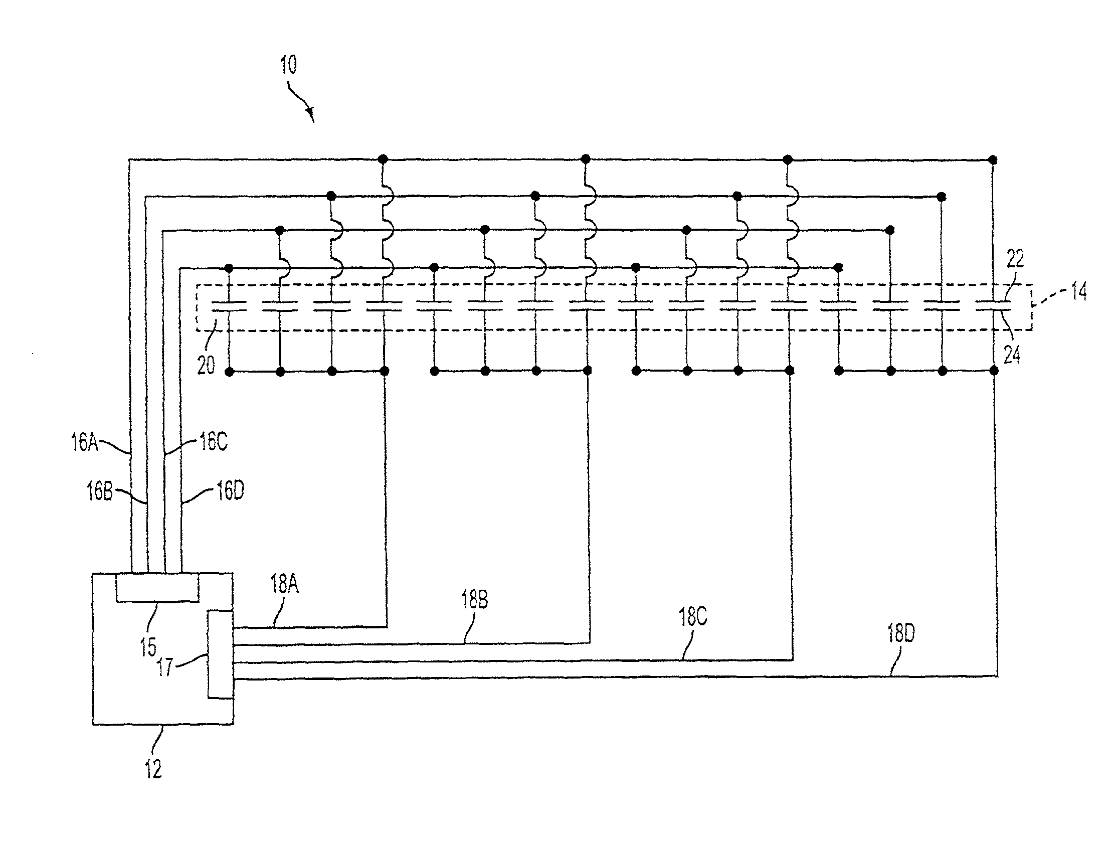
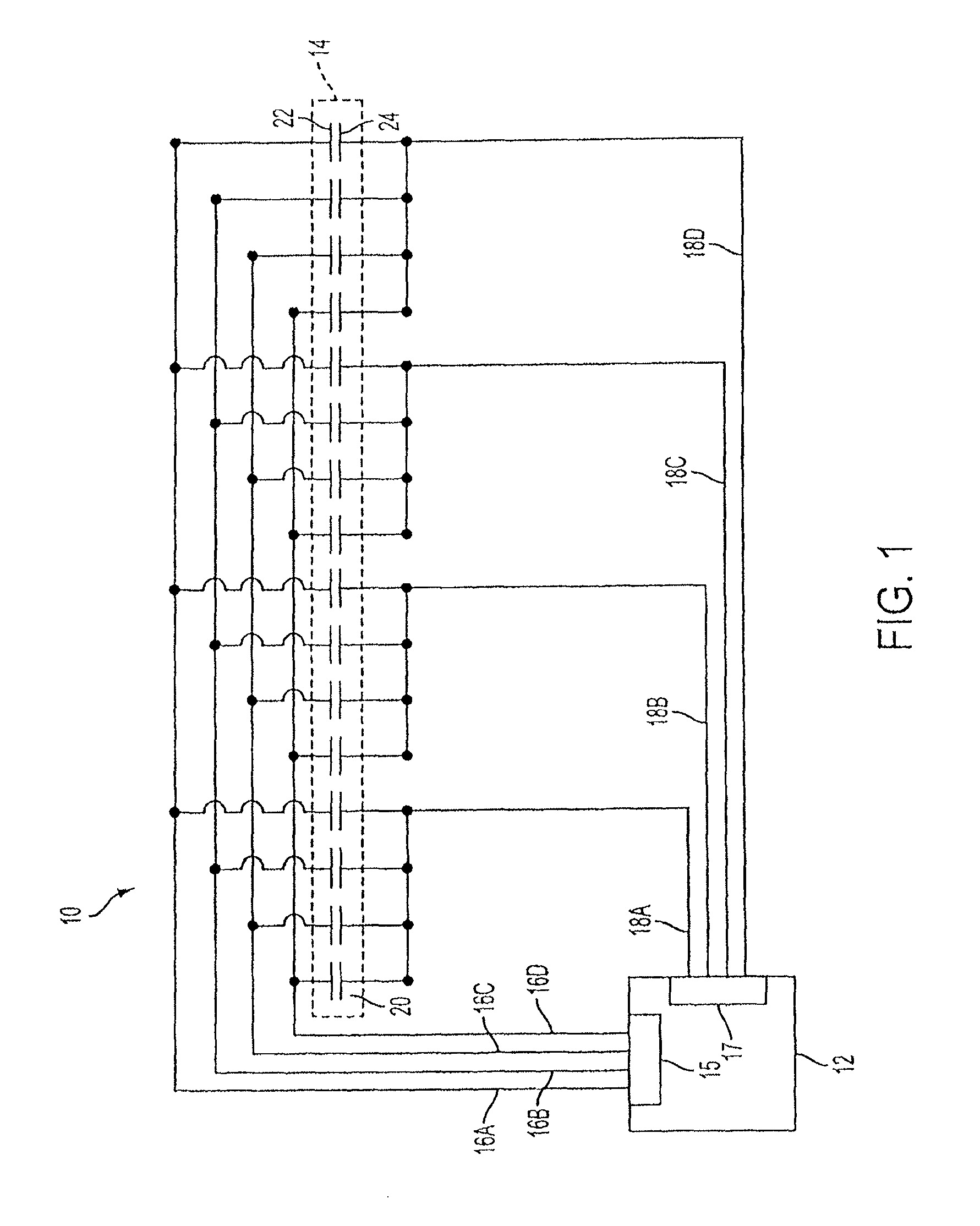
[0045]The simplicity of capacitance can allow for a great deal of flexibility in design and construction of a sensing device. By way of example, the sensing device may be based on self capacitance or mutual capacitance.

[0046]In self capacitance, each of the sensing points can be provided by an individually charged electrode. As an object approaches the surface of the touch device, the object can capacitively couple to those electrodes in close proximity of the object, thereby stealing charge away from the electrodes. The amount of charge in each of the electrodes can be measured by the sensing circuit to determi...


PUM


Abstract

A mutual capacitive touch sensing device is disclosed. The device can include nodes for sensing a touch at the device and for sensing a force applied to the device. Some nodes can perform both touch and force sensing; while other nodes can perform touch sensing. The device can include distinct individual drive lines for driving the nodes and separate distinct individual sense lines for transmitting touch or force signals from the nodes. The nodes can form groups, where the nodes in each group can be coupled to the same drive line and to different sense lines and where each node in a group can be coupled to a node in a different group by the same sense line. Each node can be set up with a different combination of drive and sense lines coupled thereto. An example device can be a click wheel.

Description

[0001]This application is a continuation of U.S. patent application Ser. No. 14 / 293,843, filed Jun. 2, 2014, which is a continuation of U.S. patent application Ser. No. 12 / 498,119, filed Jul. 6, 2009, now U.S. Pat. No. 8,743,060, which is a continuation-in-part of U.S. patent application Ser. No. 11 / 482,286, filed Jul. 6, 2006, the entire contents of which are incorporated herein by reference.[0002]This application is related to the following applications, all of which are herein incorporated by reference:[0003]U.S. patent application Ser. No. 10 / 188,182, filed Jul. 1, 2002; U.S. patent application Ser. No. 10 / 722,948, filed Nov. 25, 2003; U.S. patent application Ser. No. 10 / 643,256, filed Aug. 18, 2003; U.S. patent application Ser. No. 10 / 840,862, filed May 6, 2004; U.S. patent application Ser. No. 11 / 057,050, filed Feb. 11, 2005; U.S. patent application Ser. No. 11 / 115,539, filed Apr. 26, 2005; and U.S. patent application Ser. No. 11 / 882,420, filed Aug. 1, 2007.FIELD[0004]This rel...

Claims


Application Information

Patent Timeline
Patent Type & Authority Patents(United States)
IPC IPC(8): G06F3/044G06F3/0362G06F3/041
CPCG06F3/0362G06F3/044G06F3/0414G06F2203/04104G06F2203/04106G06F3/0445G06F3/0446
Inventor HOTELLING, STEVEN P.
Owner APPLE INC
Why Eureka
Try Eureka