Light assembly for spray paint gun

a technology of spray paint and assembly, which is applied in the direction of screwdrivers, lighting elements, wrenches, etc., can solve the problems of difficulty in visualizing the surface as the painter is receiving paint, and achieve the effect of easy visualizing the pain

Active Publication Date: 2016-08-09
LUCAS KIRK THOMAS
View PDF6 Cites 15 Cited by
  • Summary
  • Abstract
  • Description
  • Claims
  • Application Information

AI Technical Summary

Benefits of technology

[0005]The above stated need is addressed by a light assembly for spray paint guns. The light assembly is adapted for mounting to a paint spray gun of the type having a handle, a gravity feeding paint container mounted above the handle having a neck portion that is received by a paint inlet fitting at the top of the handle and a forwardly projecting nozzle assembly including an externally threaded generally cylindrical nozzle portion and a removable internally threaded spray nozzle fitting that threads onto the nozzle portion. The light assembly includes a light bracket, light modules and a power pack. The light bracket is shaped to fit around the paint gun nozzle and includes a generally flat thin mounting plate portion having a generally circular opening that receives the nozzle portion of the spray gun. The light bracket generally hangs on the nozzle portion and is held in place when the spray nozzle fitting is threaded onto the externally threaded nozzle portion. The light bracket includes a top flange that extends back from the top edge of the mounting plate. The rear edge of the top flange of the light bracket has at least one centered scallop that receives the paint inlet fitting at the top of the handle. Thus, when the nozzle fitting is threaded into place, the light bracket is pushed back so that the scallop of the top flange engages the paint inlet fitting. The light modules are secured to the light bracket. A power pack is also secured to the light bracket. In this example, the power pack is also mounted to the light bracket and is adapted to hold standard sized small batteries, such as, for example, a set of AAA batteries. Preferably a switch is provided in a circuit that includes the batteries and the light modules. In this example, the lights include a plurality of compact LED lights that are arranged around the nozzle assembly in light modules and are selected, arranged and oriented to produce a generally uniform area of illumination that encompasses the paint spray pattern area. Accordingly, with the lights activated, the painter is able to easily see the paint as it is sprayed on to a workpiece surface.

Problems solved by technology

Unfortunately, it is often the case that the painter is positioned between the light source and the surface being painted.
This causes a shadow to be cast on the work surface that, in turn, makes it difficult for the painter to visualize the surface as it is receiving paint.

Method used


Image

  • Light assembly for spray paint gun
  • Light assembly for spray paint gun
  • Light assembly for spray paint gun

Examples


second embodiment

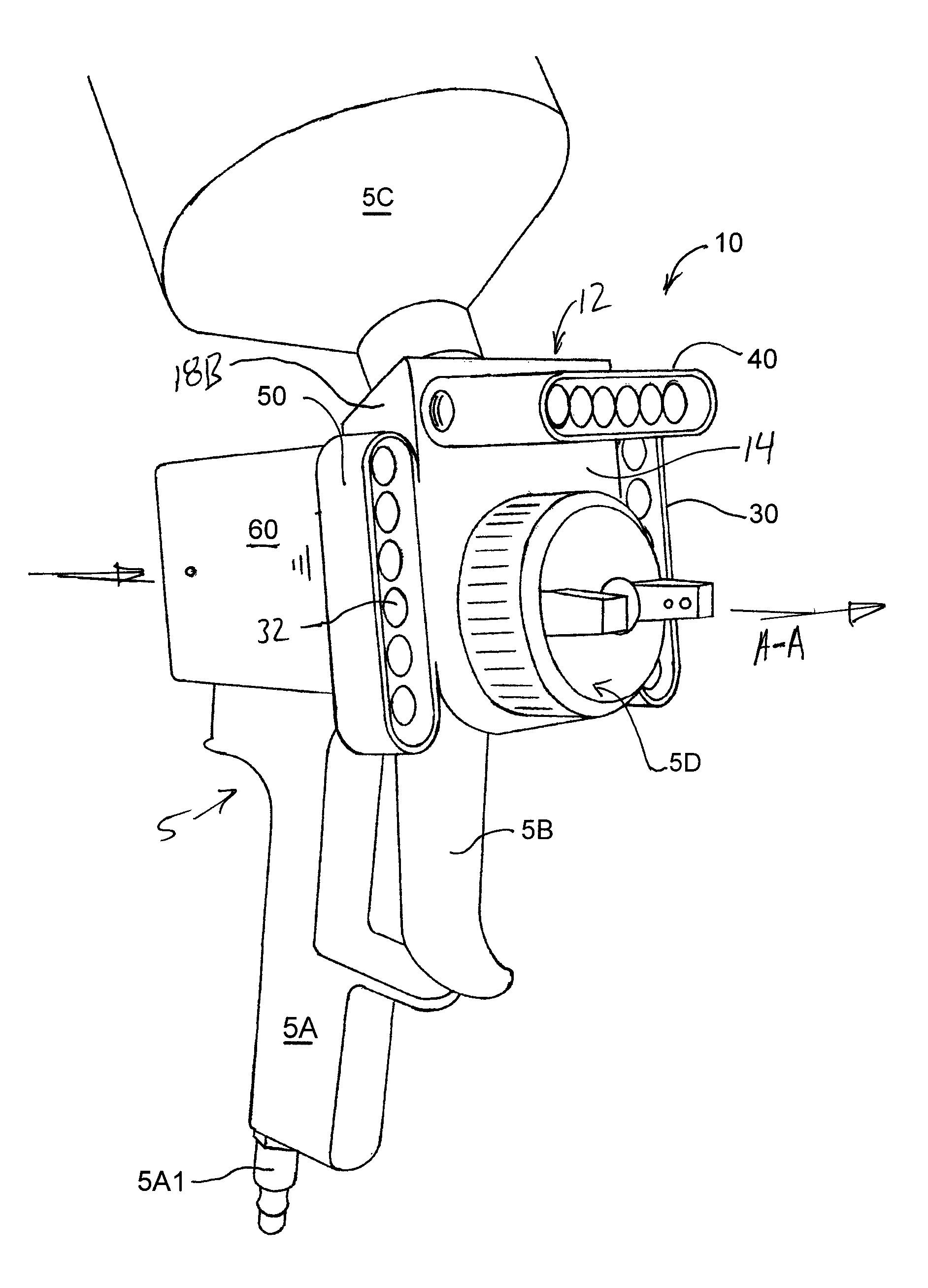
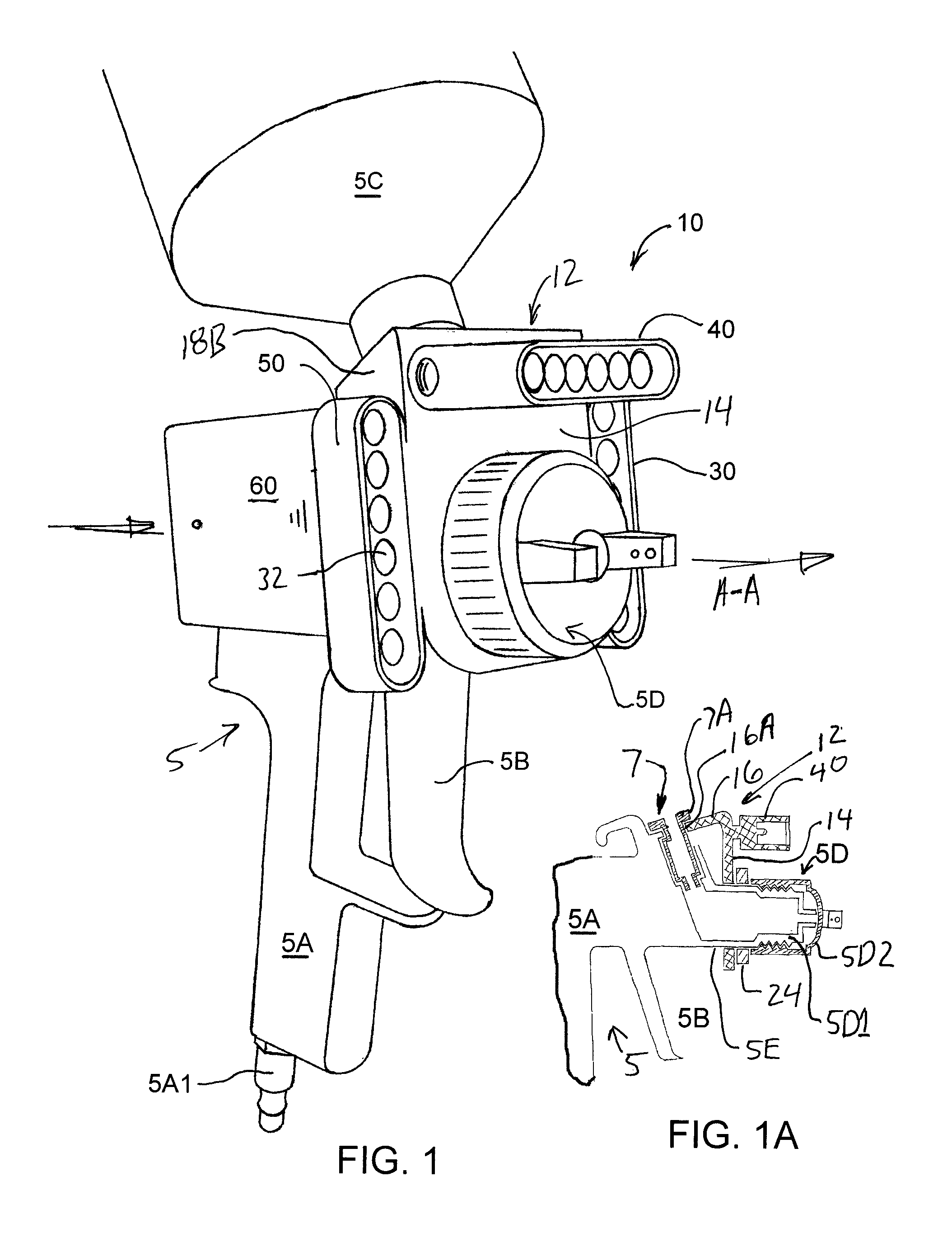
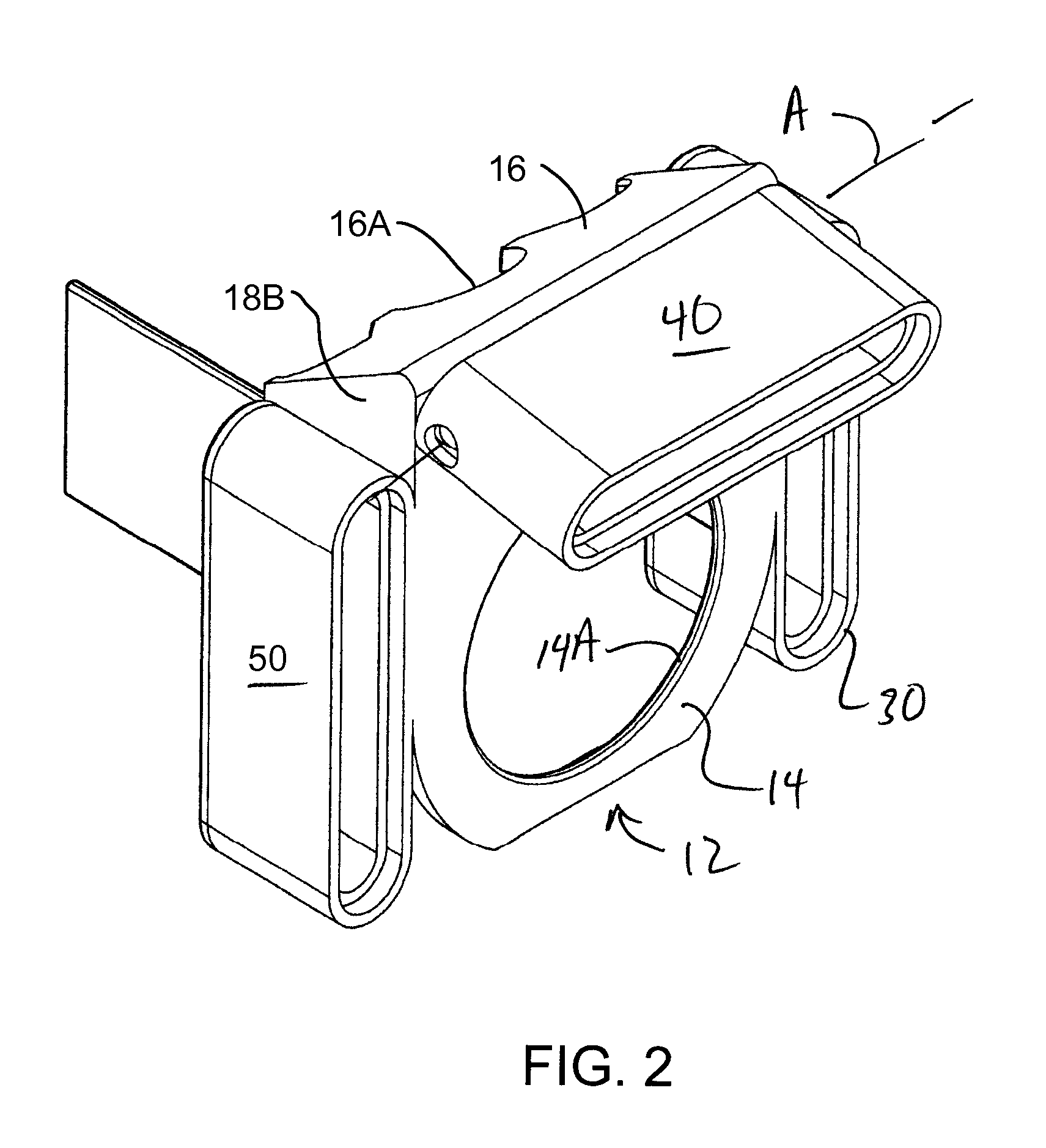
[0031]As noted above, light assembly 10 includes a first light module 30, a second light module 40 and a third light module 50. First light module 30 is mounted to the left side of light bracket 12 on a left flange 18A that extends between front mounting plate portion 14 and top flange 16. Second light module 40 is mounted to the top edge of light bracket 12 near the top edge of front mounting plate portion 14. Third light module 50 is mounted to the right side of light bracket 12 on a right flange 18B that also extends between front mounting plate portion 14 and top flange 16. In this example, each light module, 30, 40 and 50 includes a linear pattern of lights which are preferably six LED lights 32. In this example, second light module 40 is mounted on a pivot to pivot around axis A indicated in FIG. 1. The pivotable mounting of second light module 40 allows the operator to adjust the direction of the lights of second module 40. In this example, the LED lights 32 of first, second ...

third embodiment

[0036]FIGS. 6-10 illustrate a third embodiment spray gun light assembly 210. As can be seen in FIG. 5, light assembly 210 includes a body 212 and a battery pack 260 which in this example is fixed to body 212. Body 212 includes a central opening 214 adapted for receiving the nozzle of a paint gun. Body 212 also includes two opposite light modules 216. Preferably, light modules 216 are symmetrically spaced on either side of the paint nozzle in order to not effect the center of gravity of the paint nozzle as much as possible. Also preferably, light modules 216 are positioned behind the spray nozzle so that light is emanating from behind the point were spraying paint originates. In this example, each light module carries one very intense LED light source 217. Preferably, each light source 217 has a light output of about 200 lumens. In this example, two CREE XM-L white LEDs are selected which each have an output of about 200 lumens or a combined output of about 400 lumens. Two such LED l...

fourth embodiment

[0046]Another aspect of fourth embodiment light assembly 310 is the battery compartment 360 shown in FIGS. 16A and 16B. An important aspect of battery module 360 is to provide a battery compartment and switching mechanism that cannot be effected by spray paint. Typically, spray paint would tend to accumulate and foul devices with a conventional switch. As can be seen in FIG. 16A, battery B, which, in this example, is a typical compact nine volt battery, is enclosed in water tight compartment 362. Battery module 360 also includes a switch mechanism 370. Compartment 362 is closed by a sealed cap 364 which, in this example, is sealed by an O ring 366. As can be seen in FIGS. 16A and 16B, battery B is capable of sliding between a non-contact position shown in FIG. 16A and a contact position shown in FIG. 16B. When in the non-contact position, battery terminals BT1 and BT2 are not in contact with light circuit contacts C1 and C2 respectively. A spring 368 biases battery B in the non-cont...


PUM


Abstract

A compact light assembly is adapted for use with a spray paint gun. The spray paint gun has a spray gun body and a spray nozzle assembly including a nozzle fitting and a spray nozzle that threads onto the nozzle fitting. The light assembly includes a light bracket, LED lights, a battery pack and a switch. The light bracket has a mounting plate which has an opening for receiving the nozzle fitting of the spray nozzle assembly. The light bracket receives the nozzle fitting and the spray nozzle is threaded onto the nozzle fitting until the mounting plate. The LED lights, the battery pack and the switch are also mounted to the light bracket. The LED lights are arranged around the nozzle and shine light on an area that includes the area receiving paint from the paint gun.

Description

RELATED APPLICATIONS[0001]This application is a continuation-in-part of U.S. non-provisional patent application Ser. No. 13 / 564,905 filed on Aug. 2, 2012, which is incorporated herein by reference.[0002]U.S. Non-provisional patent application Ser. No. 13 / 564,905 claimed the benefit of U.S. Provisional Patent Application Ser. No. 61 / 514,328 having an application date of Aug. 2, 2011 which is also incorporate herein by reference.FIELD OF THE INVENTION[0003]The present invention relates to a light assembly that can be mounted to paint spray gun for illuminating an area being painted by a paint sprayer.BACKGROUND OF THE INVENTION[0004]The process of spraying paint on a surface, particularly spraying paint on the surface of a vehicle such as an automobile, is a process that requires a high degree of skill if a coating of paint is to be applied to a surface that is uniform and flawless. Typically, the paint is applied using a hand held paint gun that is connected to a pressurized air sour...

Claims


Application Information

Patent Timeline
Patent Type & Authority Patents(United States)
IPC IPC(8): B25B23/18F21V33/00B05B15/00
CPCB05B15/00F21V33/00B05B7/2478
Inventor LUCAS, KIRK THOMAS
Owner LUCAS KIRK THOMAS
Why Eureka
Try Eureka