Image forming apparatus

a technology of image forming and forming rollers, which is applied in the direction of electrographic process apparatus, instruments, optics, etc., can solve the problems of insufficient toner supply to the developing roller, development ghost, and inability to produce sufficient toner, so as to prevent the occurrence of solid image compliance defects, prolong the service life, and suppress the effect of development ghos

Active Publication Date: 2016-08-09
CANON KK
View PDF10 Cites 5 Cited by
  • Summary
  • Abstract
  • Description
  • Claims
  • Application Information

AI Technical Summary

Benefits of technology

[0009]An object of the present invention is to provide an image forming apparatus capable of suppressing development ghost, preventing solid image compliance defects, and extending its service life.
[0038]According to the aspects of the present invention, it is possible to suppress development ghost which may occur when toner deterioration is suppressed and to prevent the occurrence of solid image compliance defects. Due to this, it is possible to provide a high-quality image forming apparatus capable of extending its service life.

Problems solved by technology

As a result, a difference in the toner charge amount resulting from a difference in printing pattern may occur and development ghost may occur.
In this case, however, a sufficient amount of toner is not supplied to the developing roller during the image forming operation.
As a result, when an image having a high printing ratio such as a full solid image is printed, image voids (hereinafter referred to as “solid image compliance defects”) which are images that are not printed due to an insufficient amount of toner supply may occur.

Method used


Image

  • Image forming apparatus
  • Image forming apparatus
  • Image forming apparatus

Examples


embodiment

Image Forming Apparatus

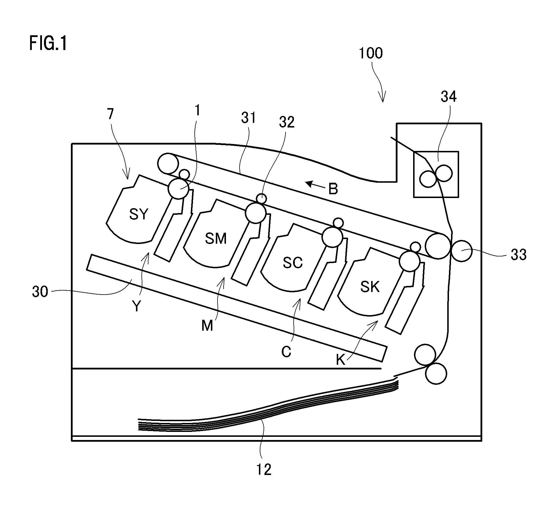
[0050]An overall configuration of an electrophotographic image forming apparatus (image forming apparatus) according to an embodiment of the present invention will be described with reference to FIG. 1. FIG. 1 is a schematic cross-sectional view of an image forming apparatus 100 according to the present embodiment. In the present embodiment, a case where the present invention is applied to a full-color laser beam printer which employs an in-line system and an intermediate transfer system will be described as an example of an image forming apparatus. The image forming apparatus 100 can form a full-color image on a recording material (for example, recording paper, a plastic sheet, and a cloth) according to image information. The image information is input to the main body of the image forming apparatus from an image reading apparatus which is connected to the image forming apparatus, or from a host device, such as a personal computer, which is connected in a com...

example 1

Control of Supply Roller Bias

[0086]Control of bias between the developing roller 4 and the supply roller 5 according to Example 1 of the present invention will be described with reference to FIG. 3. FIG. 3 is a timing chart illustrating the bias control when one sheet is printed, for comparison between Example 1 and Comparative Examples.

[0087]Here, respective time-points in the timing chart will be described in detail. The following time-points are the time-points during printing (image forming operation) of one sheet of recording material.

[0088]The time-point “start of development driving” is a time-point at which the developing roller 4 and the supply roller 5 receive the driving force of the driving motor as the development drive unit (b) and start rotating.

[0089]The time-point “start of image formation” is a time-point at which laser exposure in the sub-scanning direction starts.

[0090]The time-point “end of image formation” is a time-point at which the laser exposure in the sub-...

example 2

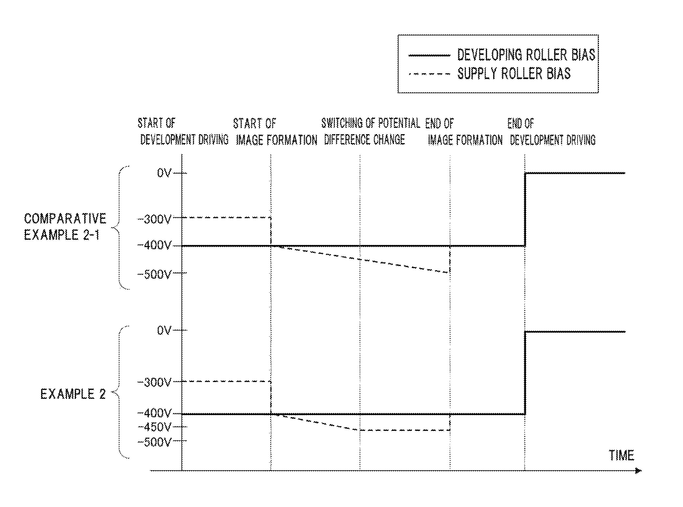
[0116]An image forming apparatus according to Example 2 of the present invention performs control of changing an inclination of a change in a supply roller bias at a predetermined time-point during the image formation period. The advantages of this control appear remarkable when an image which is likely to cause development ghost is printed in the latter half of a sheet. With the control of the present example, it is possible to diminish the occurrence of development ghost even when such an image is printed. In the description of Example 2, description of the portions overlapping those of Example 1 will not be provided.

[0117]The control according to Example 2 will be described with reference to a timing chart of FIG. 4. FIG. 4 is a timing chart illustrating bias control when one sheet is printed, for comparison between Comparative Example 2-1 (Example 1) and Example 2. As illustrated in FIG. 4, a time-point “switching of potential difference change” is provided at a predetermined ti...


PUM


Abstract

An image forming apparatus includes a developer bearing member, a developing bias application unit, a developer supply member, and a supply bias application unit that applies a supply bias to the developer supply member. In a predetermined period before a start of image formation during an image forming operation for an image formed on one recording material, the supply bias application unit applies a supply bias of which the magnitude of an absolute value is smaller than that of a developing bias, to the developer supply member. In a period between the start of image formation and an end of image formation during the image forming operation, the supply bias application unit applies a supply bias to the developer supply member so that a difference in the magnitude of the absolute value from the supply bias in the predetermined period before the start of image formation increases gradually.

Description

BACKGROUND OF THE INVENTION[0001]1. Field of the Invention[0002]The present invention relates to an image forming apparatus.[0003]2. Description of the Related Art[0004]An electrophotographic apparatus or an electrostatic recording apparatus (hereinafter, an image forming apparatus) such as a copying machine, a printer, or a facsimile includes a developing assembly for visualizing an electrostatic latent image using a non-magnetic single-component toner. Conventionally, a developing assembly which includes a developing roller as a developer bearing member for bearing and conveying toner and a supply roller disposed around the developing roller and serving as a developer supply member for supplying toner to the developing roller is known. In this developing assembly, toner is supplied to the developing roller while being triboelectrically charged by mechanical rubbing between the supply roller and the developing roller. The supplied toner, of which the thickness of a toner layer on t...

Claims


Application Information

Patent Timeline
Patent Type & Authority Patents(United States)
IPC IPC(8): G03G15/08G03G15/06
CPCG03G15/065G03G2215/0132
Inventor HAYASHI, KODAIMITSUI, YOSHIHIROFUKUSHIMA, NAOKIKAWASAKI, SHUHEI
Owner CANON KK
Why Eureka
Try Eureka