Conveyer apparatus for discharging chips

a conveyer and chips technology, applied in the direction of transportation and packaging, manufacturing tools, cleaning using liquids, etc., can solve the problems of fine cutting chips infiltrating into the portion of the filtering drum where the filtering drum is located, and the filter may be damaged

Active Publication Date: 2016-08-16
O SUNG MECHATRONICS
View PDF25 Cites 6 Cited by
  • Summary
  • Abstract
  • Description
  • Claims
  • Application Information

AI Technical Summary

Benefits of technology

[0012]Accordingly, the present invention has been made keeping in mind various problems occurring in the prior art, and an object of the present invention is to provide a new type of conveyer apparatus for discharging chips that enables cutting chips entering into the inner space of a conveyer unit to be smoothly discharged into the outer space of the conveyer unit, thereby preventing a filter provided in the inner space of the conveyer unit from being damaged by the cutting chips.

Problems solved by technology

However, the filtering drum is problematic in that its filter may be damaged because when the filtering drum is simply installed within the cutting oil tank, it is exposed to cutting chips discharged via a conveyer.
However, the above conventional technology configured as described above still causes a concern about fine cutting chips infiltrating into a portion where the filtering drum is located, i.e., the inside of a portion through which the corresponding conveyer passes, via various gaps of the conveyer.
Cutting chips infiltrating into the inner side of the conveyer cannot be easily discharged, and thus they are unavoidably stacked on the inner portion of the conveyer.
Accordingly, concerns about the clogging of the meshes of the filter of the filtering drum and damage thereto still remain.
Therefore, an operator suffers from inconvenience in which he or she must continuously clean the inner portion of the conveyer of the conveyer apparatus for discharging chips.
In particular, to clean the inner portion of the conveyer, the conveyer must be disassembled, and problems arise in that the disassembly work is very complicated and a long period of time is required.

Method used


Image

  • Conveyer apparatus for discharging chips
  • Conveyer apparatus for discharging chips
  • Conveyer apparatus for discharging chips

Examples


Embodiment Construction

[0029]A conveyer apparatus for discharging chips according an embodiment of the present invention will be described with reference to FIGS. 1 to 10 below.

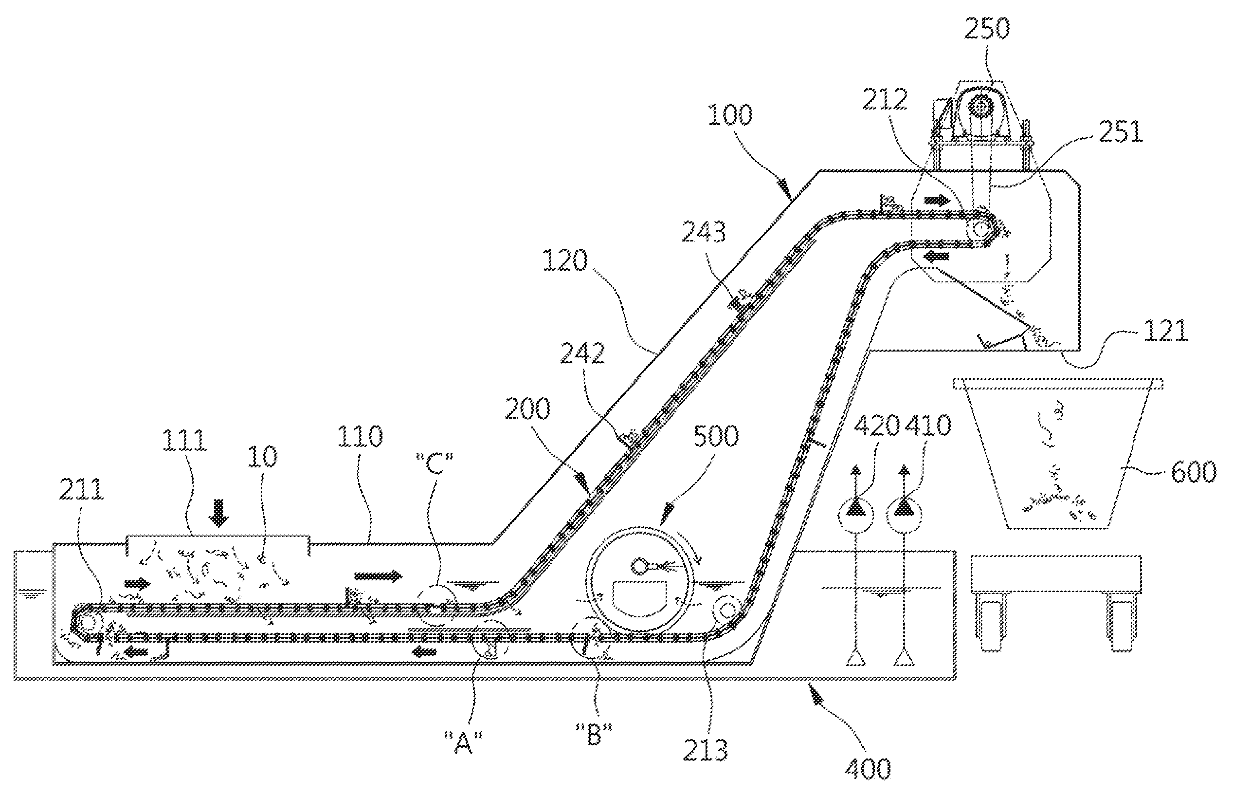
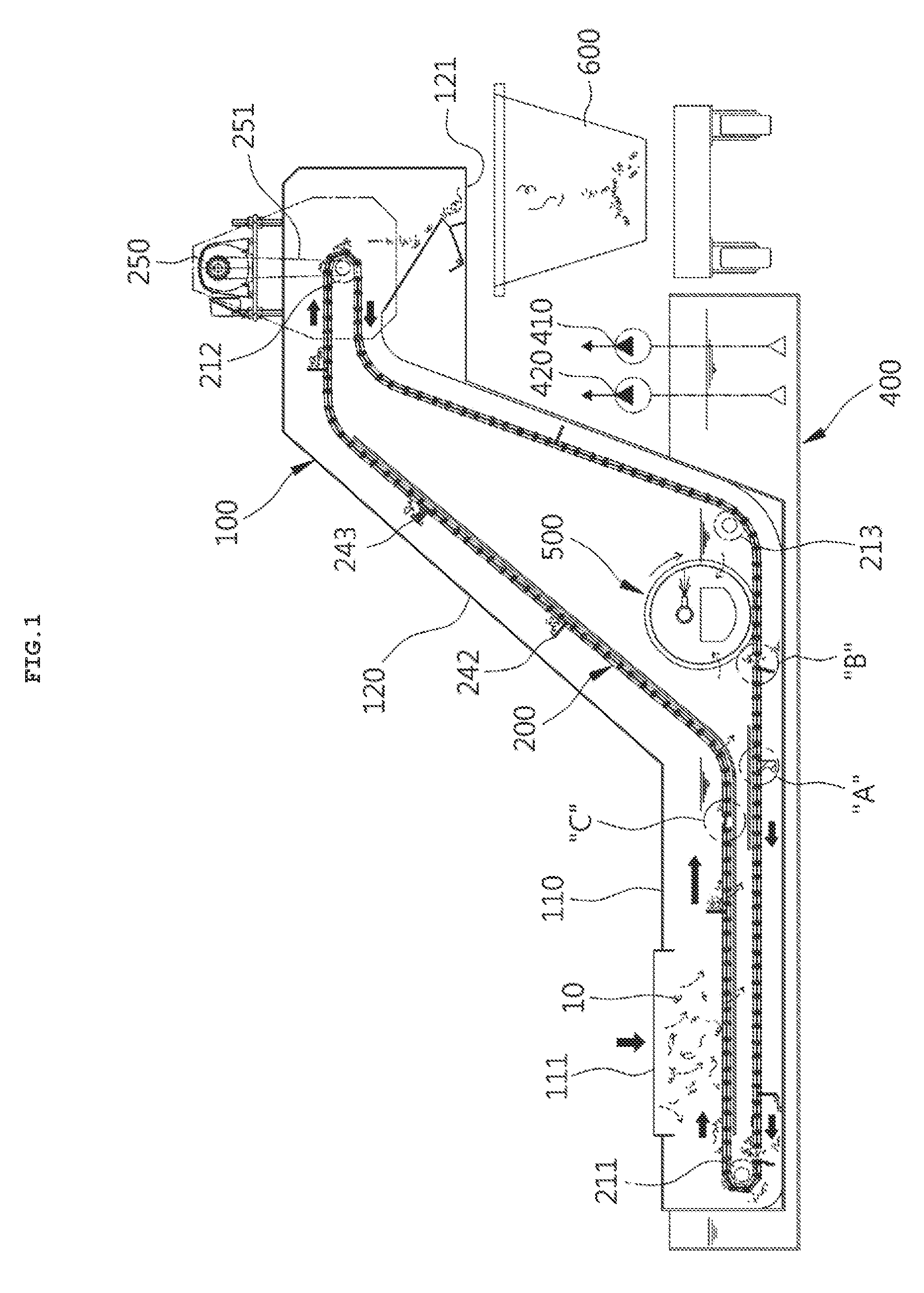
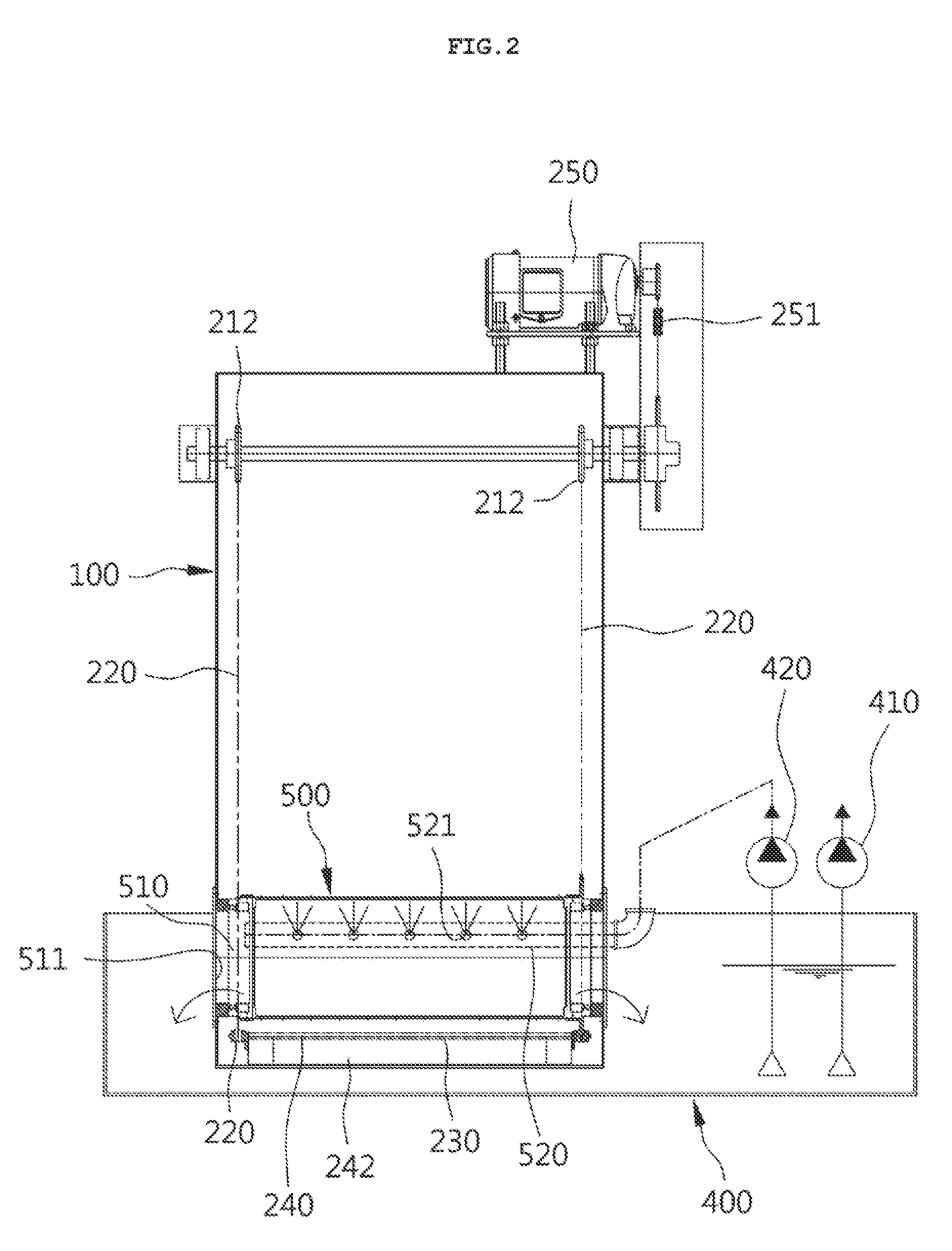
[0030]FIG. 1 is a front view illustrating a conveyer apparatus for discharging chips according to an embodiment of the present invention, FIG. 2 is a side view illustrating the apparatus for discharging chips according to the embodiment of the present invention conveyer, and FIG. 3 is a perspective view illustrating the conveyer unit and opening / closing unit of the conveyer apparatus for discharging chips according to the embodiment of the present invention.

[0031]As shown in these drawings, the conveyer apparatus for discharging chips (hereinafter referred to as the “conveyer apparatus”) according to the embodiment of the present invention basically includes a tank body 100, a conveyer unit 200, and an opening / closing unit 300. In particular, the conveyer unit 200 is configured to have an opening 201 adapted to allow the inside and...


PUM

PropertyMeasurementUnit
weightaaaaaaaaaa
timeaaaaaaaaaa
structureaaaaaaaaaa

Abstract

A conveyer apparatus for discharging chips is disclosed herein. The conveyer apparatus includes a tank body, a conveyer unit, and an opening / closing unit. The tank body is configured such that the tank body is configured in the form of a container body, an inlet is formed in the top surface of one side of the tank body, and a chip outlet is formed in the bottom surface of the remaining side of the tank body. The conveyer unit is installed in the form of a caterpillar spaced apart from the inner walls of the tank body, and has at least one opening so that the inner and outer spaces of the conveyer unit communicate. The opening / closing unit is installed to block the opening, and operates so as to open the opening when the corresponding opening passes through a surface opposite the inner bottom surface of the tank body.

Description

CROSS REFERENCE TO PRIOR APPLICATION[0001]This application claims priority to Korean Patent Application No. 10-2014-0091123 (filed on Jul. 18, 2014), which is hereby incorporated by reference in its entirety.BACKGROUND[0002]1. Technical Field[0003]The present invention relates generally to a conveyer apparatus and, more particularly, to a new type of conveyer apparatus for discharging chips that enables cutting chips entering into the inner space of a conveyer unit to be discharged into the outer space of the conveyer unit, thereby preventing a filtering drum provided in the inner space of the conveyer unit from being damaged by the cutting chips.[0004]2. Description of the Related Art[0005]In general, conveyer apparatuses for discharging chips are provided in various machine tools (for example, lathes, drilling machines, milling machines, machining centers, etc.), and extract cutting chips from the cutting chips and cutting oil generated when a workpiece is machined by a correspond...

Claims


Application Information

Patent Timeline
Patent Type & Authority Patents(United States)
IPC IPC(8): B65G45/22B08B3/04B23Q11/10B23Q11/00B01D43/00
CPCB23Q11/0057B23Q11/1069Y02P70/171Y02P70/10
Inventor TAK, KEUMSUKGU, WONCHOL
Owner O SUNG MECHATRONICS
Why Eureka
Try Eureka