Supercharge Your Innovation With Domain-Expert AI Agents!

Optical encoder with a scale that has fine and coarse pitch patterns

a pitch pattern and encoder technology, applied in the field of optical encoders, can solve problems such as errors in position detection, loss of position information, and accumulation of errors

Active Publication Date: 2016-08-16
CANON KK
View PDF8 Cites 6 Cited by
  • Summary
  • Abstract
  • Description
  • Claims
  • Application Information

AI Technical Summary

Problems solved by technology

Although the configuration of the incremental method is simple, there are problems that position information is lost when power is turned off and errors are accumulated by exogenous noise.
When performing analysis on the basis of the prior example, it is found that a light intensity distribution, which is reflected from a scale including a plurality of modulation pitches, includes unnecessary spatial frequency components that may cause errors in position detection.
Specifically, in the prior example, although the light intensity distribution corresponds to a sum of a modulation component A corresponding to a fine pitch pattern and a modulation component B corresponding to a coarse pitch pattern, the light intensity distribution includes unnecessary spatial frequency components (A+B, A−B, and further, components due to unnecessary diffracted light) that may cause errors in position detection.
By the effect of the above, an error from an ideal sine wave occurs.
As a result, there is a problem that a position detection error occurs when converting the sine wave into a position signal by an arctangent calculation.

Method used


Image

  • Optical encoder with a scale that has fine and coarse pitch patterns
  • Optical encoder with a scale that has fine and coarse pitch patterns
  • Optical encoder with a scale that has fine and coarse pitch patterns

Examples


first embodiment

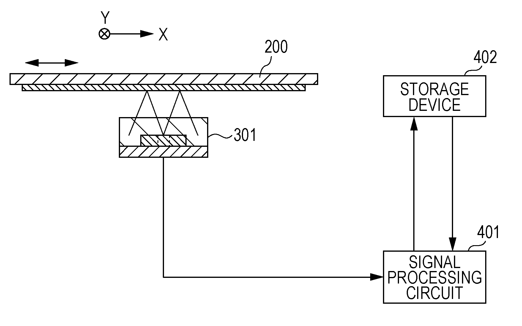
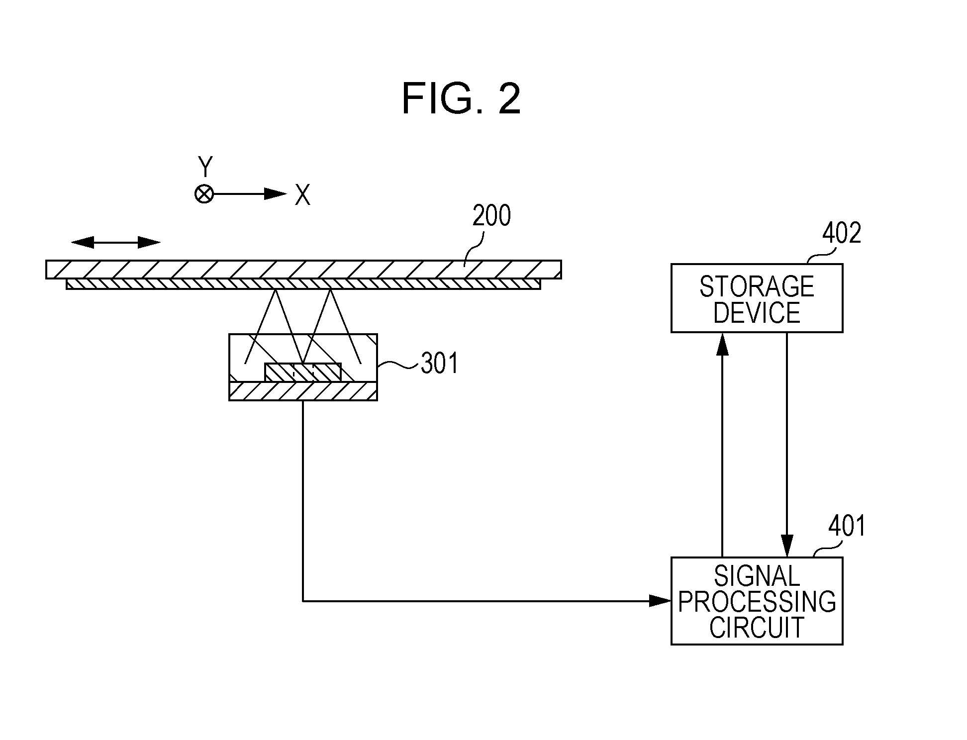
[0029]The present embodiment is an optical encoder of an absolute method that can output a relative value of position as well as an absolute value of position. FIG. 2 shows a configuration of the optical encoder of the present embodiment. The encoder includes a scale 200 attached to a movable portion, a sensor unit 301 attached to a fixed portion, a signal processing circuit 401, and a storage device 402. The signal processing circuit 401 performs interpolation processing of the encoder signal obtained by the sensor unit 301, reads and writes a signal from and to a storage device 402, and outputs a position signal.

[0030]To obtain a relative value output related to a position in order to measure a relative moving distance, a pair of a slit track 201 as shown in FIG. 4 and a photodiode array 311 as shown in FIGS. 5 and 6 may be used. The slit track 201 includes a fine pitch pattern and a coarse pitch pattern in one track. The photodiode array 311 is a common photodiode array used to d...

second embodiment

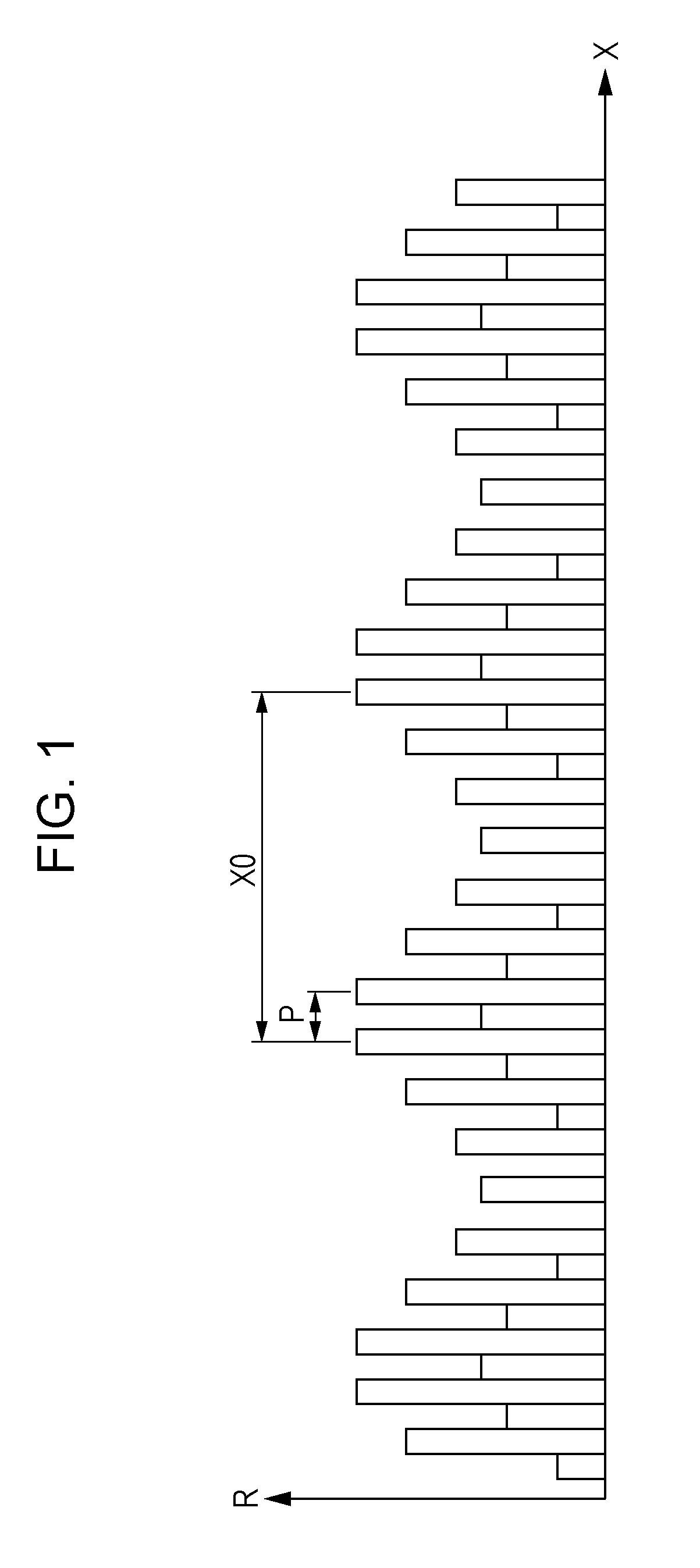
[0073]In the present embodiment, the pattern of the scale 200 is different from that of the first embodiment. The configuration other than the above and the signal processing are the same as those in the first embodiment, so that the description thereof will be omitted. FIG. 10 shows an enlarged diagram of a part of the first track 201 and the second track 202 of the scale 200. The first track 201 has a pattern in which unit block patterns 211 are periodically arranged in the measuring direction (X axis direction) and a direction (Y axis direction) perpendicular to the measuring direction, respectively. The unit block pattern 211 of the first track 201 has an X-direction width X0 of 700 μm and an Y-direction width Y0 of 50 μm.

[0074]The unit block pattern 211 includes an area (area A) of a pattern row in which patterns having an X-direction width of 50 μm are arranged at a pitch P of 100 μm at regular intervals and an area (area B) of a modulation pattern row in which patterns are ar...

third embodiment

[0079]In the present embodiment, the pattern of the scale 200 is different from that of the first embodiment. The detection pitch of the sensor is switched between 100 μm and 600 μm. The configuration other than the above and the signal processing are the same as those in the first embodiment, so that the description thereof will be omitted. FIG. 12 shows a scale pattern of the first track 201 and the second track 202 according to the present embodiment.

[0080]The first track 201 has areas (areas C) of a pattern row in which patterns having an X-direction width of 50 μm are arranged at a pitch P=100 μm at regular intervals on both sides of the sensor scanning area. Further, the first track 201 has an area (area D) formed of a reflective film pattern in which a boundary line between a reflective portion and a non-reflective portion is formed into a sinusoidal wave shape having a pitch of X0=600 μm in the center portion of the sensor scanning area. The Y-direction width of the area D i...


PUM


Abstract

An optical encoder includes a light source, a scale which is irradiated by the light source and has a fine pitch pattern and a coarse pitch pattern in a measuring direction in one track, a high resolution detection sensor array which receives light from the scale and detects the fine pitch pattern, and a low resolution detection sensor array which receives light from the scale and detects the coarse pitch pattern. A transmittance distribution or a reflectivity distribution of the scale is a distribution obtained by summing up a modulation component which corresponds to the fine pitch pattern and in which integrated values in a direction perpendicular to the measuring direction form modulation amplitude uniform in the measuring direction and a modulation component which corresponds to the coarse pitch pattern and in which modulation amplitude is uniform in the measuring direction.

Description

BACKGROUND OF THE INVENTION[0001]1. Field of the Invention[0002]The present invention relates to an optical encoder that detects a position in a linear direction or a rotational direction.[0003]2. Description of the Related Art[0004]Conventionally, an encoder is used to detect position in a machine tool, a factory automation machine, and the like. A position detection method of encoder is divided roughly into an incremental method for measuring a relative moving distance, which is a relative value of a position, and an absolute method for detecting an absolute value of a position. Although the configuration of the incremental method is simple, there are problems that position information is lost when power is turned off and errors are accumulated by exogenous noise. On the other hand, an encoder of the absolute method is generally highly accurate without errors being accumulated, and has an advantage that it is not necessary to move to a home position even when power is turned off.[...

Claims


Application Information

Patent Timeline
Patent Type & Authority Patents(United States)
IPC IPC(8): G01D5/34G01D5/347
CPCG01D5/34746G01D5/34784G01D5/3473
Inventor NAGURA, CHIHIRO
Owner CANON KK
Features
  • R&D
  • Intellectual Property
  • Life Sciences
  • Materials
  • Tech Scout
  • Unparalleled Data Quality
  • Higher Quality Content
  • 60% Fewer Hallucinations
Learn More