Method and its apparatus for x-ray diffraction
a technology of x-ray diffraction and apparatus, applied in the field of x-ray diffraction, can solve problems such as deterioration in measurement precision or sensitivity, and achieve the effect of high detection precision
- Summary
- Abstract
- Description
- Claims
- Application Information
AI Technical Summary
Benefits of technology
Problems solved by technology
Method used
Image


Examples
first embodiment
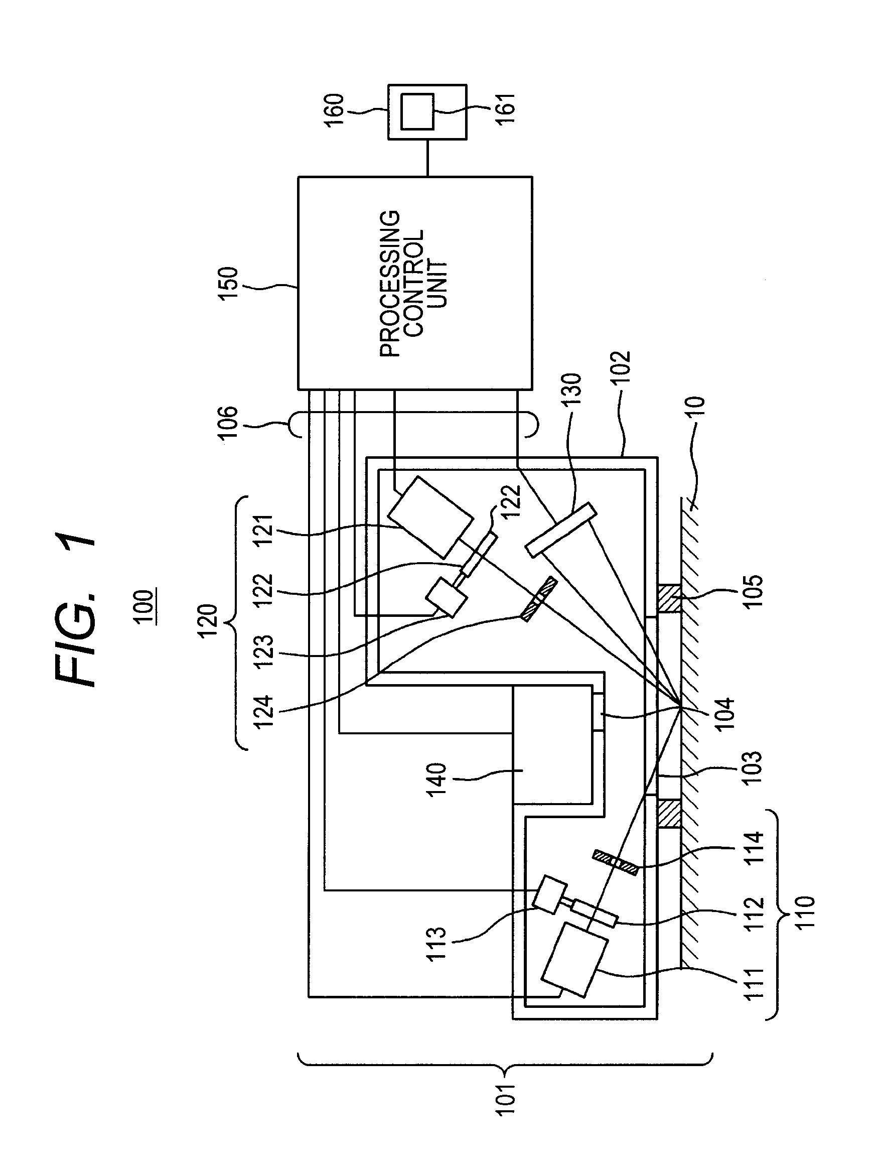
[0029]FIG. 1 illustrates a configuration of a first embodiment.
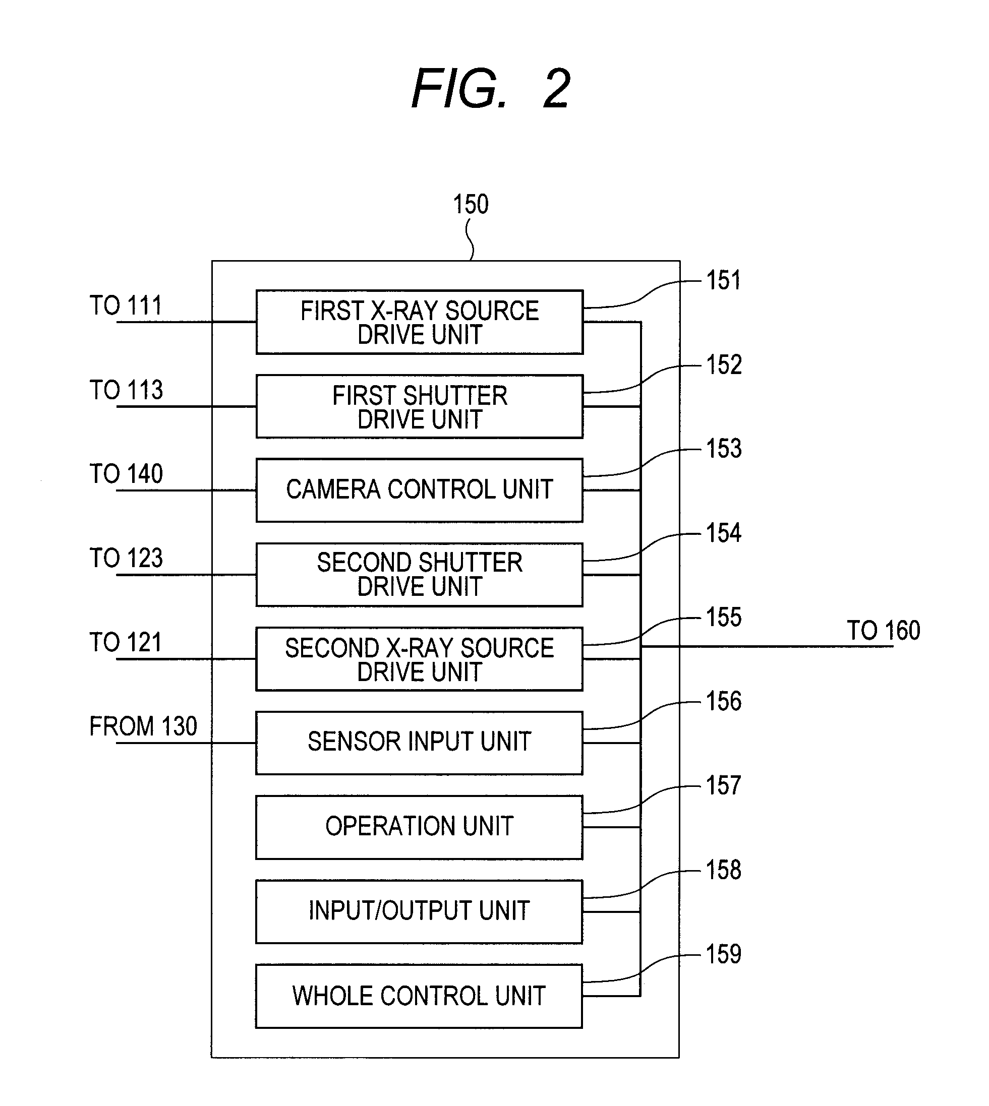
[0030]An X-ray diffraction apparatus 100 according to the first embodiment includes an X-ray diffraction apparatus body 101 having a first X-ray irradiating unit 110, a second X-ray irradiating unit 120, an X-ray detector 130, and a monitor camera 140; a processing control unit 150; and an output unit 160. The first X-ray irradiating unit 110, the second X-ray irradiating unit 120, and the X-ray detector 130 are arranged on the same plane illustrated in FIG. 1.
[0031]The first X-ray irradiating unit 110 of the X-ray diffraction apparatus body 101 includes a first X-ray source 111, a first shutter 112, a first actuator 113 that drives the first shutter 112 to open or close the shutter 112, and a first slit device 114 that narrows down the X-ray emitted from the first X-ray source 111.
[0032]The second X-ray irradiating unit 120 of the X-ray diffraction apparatus body 101 includes a second X-ray source 121, a second shutter ...
second embodiment
[0066]A second embodiment will be described below wherein the X-ray is simultaneously emitted from the first X-ray source 111 and the second X-ray source 121 so as to simultaneously irradiate the same region on the sample 10 with the use of the X-ray diffraction apparatus 100 having the configuration illustrated in FIG. 1. In this case, the pattern, as described in FIG. 5, is detected from the sample 10, wherein the pattern has the X-ray diffraction patterns by the irradiation of the X-ray from the first X-ray source 111 and the X-ray diffraction patterns by the irradiation of the X-ray from the second X-ray source 121, those of which are superimposed with each other.
[0067]The procedure of the detection in this case will be described with reference to FIG. 7.
[0068]Firstly, the X-ray diffraction apparatus 100 is set on the sample 10 to be measured, and with this state, the surface of the sample 10 below the transmissive window 103 is observed by the camera 140 through the window port...
third embodiment
[0078]A third embodiment according to the present invention will be described with reference to FIG. 8.
[0079]The configuration illustrated in FIG. 8 is obtained by eliminating the monitor camera 140 of the X-ray diffraction apparatus 100 described in FIG. 1 and mounting a third X-ray irradiating unit 830. The elements which are the same with that of the first embodiment are put the same number with the FIG. 1. As in the first and second embodiments, an X-ray diffraction apparatus body 801 of the third embodiment includes the first X-ray irradiating unit 110, the second X-ray irradiating unit 120, the third X-ray irradiating unit 830, and an X-ray detector 840. These are arranged on the same plane in a container 802 illustrated in FIG. 8, wherein X-rays generated by the first to third X-ray irradiating units 110, 120, and 830 are transmitted through an X-ray transmissive window 803 to be irradiated onto the sample 10.
[0080]As illustrated in FIG. 9, a processing control unit 850 inclu...
PUM
| Property | Measurement | Unit |
|---|---|---|
| wavelength | aaaaa | aaaaa |
| crystal lattice length | aaaaa | aaaaa |
| wavelength | aaaaa | aaaaa |
Abstract
Description
Claims
Application Information
 - R&D
- Intellectual Property
- Life Sciences
- Materials
- Tech Scout
- Unparalleled Data Quality
- Higher Quality Content
- 60% Fewer Hallucinations
Browse by: Latest US Patents, China's latest patents, Technical Efficacy Thesaurus, Application Domain, Technology Topic, Popular Technical Reports.
© 2025 PatSnap. All rights reserved.Legal|Privacy policy|Modern Slavery Act Transparency Statement|Sitemap|About US| Contact US: help@patsnap.com