

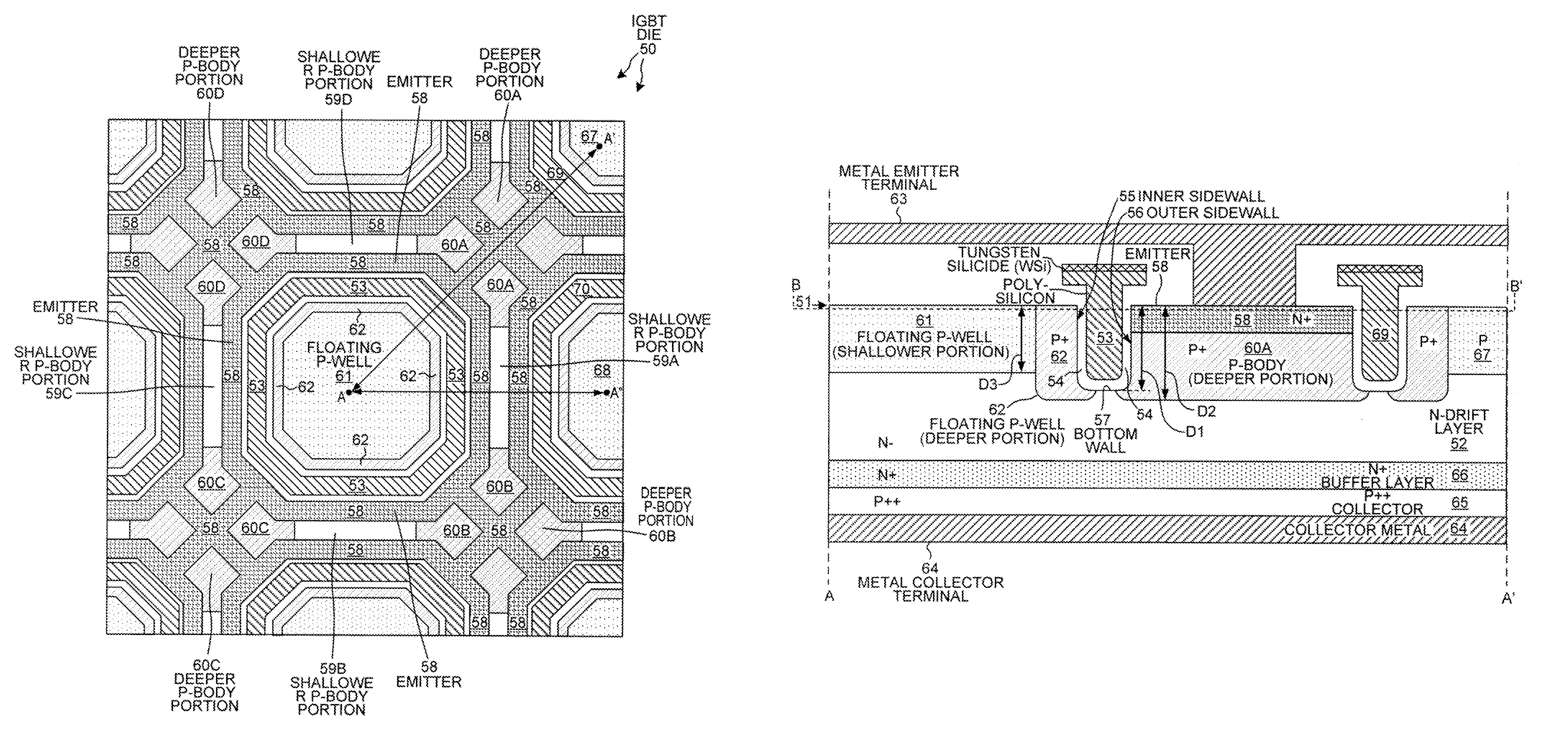
Trench IGBT with tub-shaped floating P-well and hole drains to P-body regions
a bipolar transistor and insulated gate technology, applied in the direction of basic electric elements, electrical equipment, semiconductor devices, etc., can solve the problems of gate oxide damage, avalanche breakdown of silicon in the n drift layer, etc., and achieve the effect of promoting conductivity modulation
- Summary
- Abstract
- Description
- Claims
- Application Information
AI Technical Summary
Benefits of technology
Problems solved by technology
Method used
Image

Examples
Embodiment Construction
[0034]Reference will now be made in detail to background examples and some embodiments of the invention, examples of which are illustrated in the accompanying drawings. In the description and claims below, when a first object is referred to as being disposed “over” or “on” a second object, it is to be understood that the first object can be directly on the second object, or an intervening object may be present between the first and second objects. Similarly, terms such as “upper”, “top”, “up”, “down”, “vertically”, “laterally”, “lower”, “bottom”, and “backside” are used herein to describe relative orientations between different parts of the structure being described, and it is to be understood that the overall structure being described can actually be oriented in any way in three-dimensional space. The notations N+, N−, N, P++, P+, and P are only relative, and are to be considered in context, and do not denote any particular dopant concentration range. A region denoted generally in ...
PUM
 Abstract
Description
Claims
Application Information