
Device and method for calculating dynamic variation of object

a dynamic variation and object technology, applied in image enhancement, image analysis, medical science, etc., can solve the problems of difficult to clearly distinguish an acquired ultrasonic image, difficult to precisely measure the velocity of fluid depending on an environment, and difficulty in measuring the velocity of blood flow within the left ventricl

Active Publication Date: 2016-08-23
KOREA UNIV RES & BUSINESS FOUND
View PDF21 Cites 3 Cited by
  • Summary
  • Abstract
  • Description
  • Claims
  • Application Information

AI Technical Summary

Benefits of technology

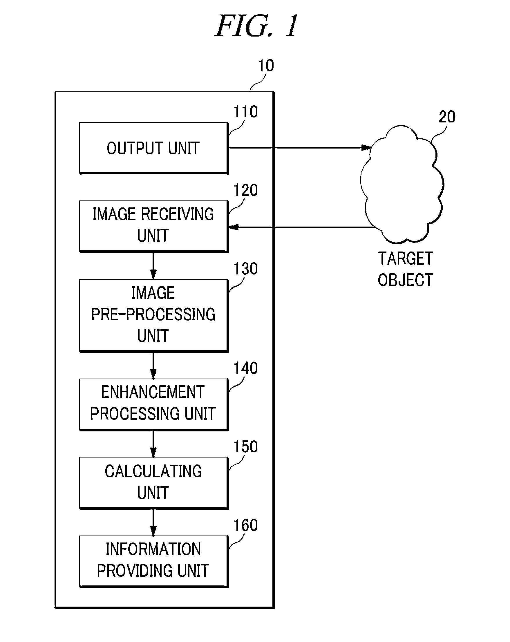
[0008]In view of the foregoing problems, example embodiments provide a device and a method for calculating dynamic variation of an object, which are capable of clearly discriminating a tracer particle and a peripheral image so as to minimize an error in velocity measurement.
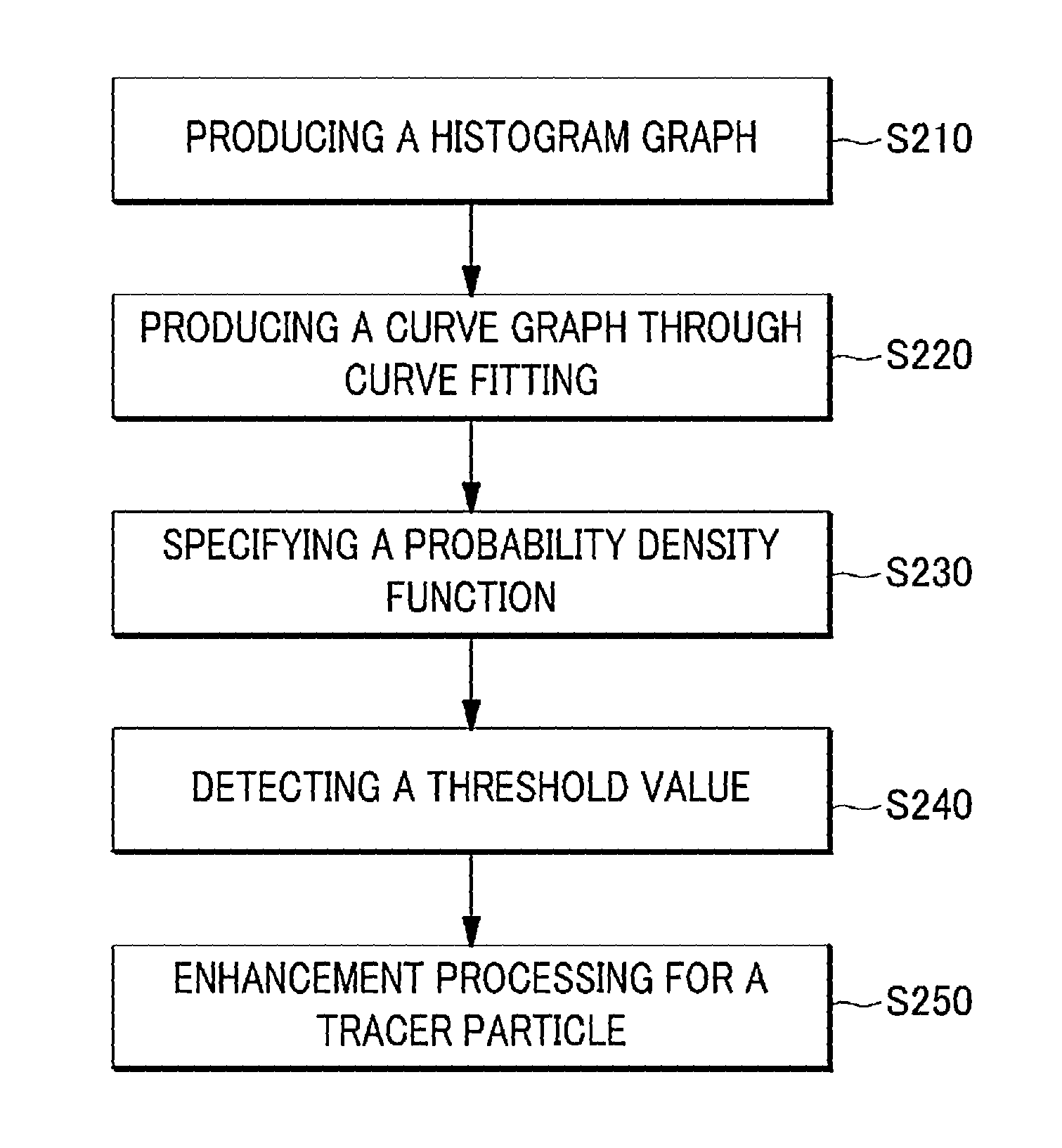
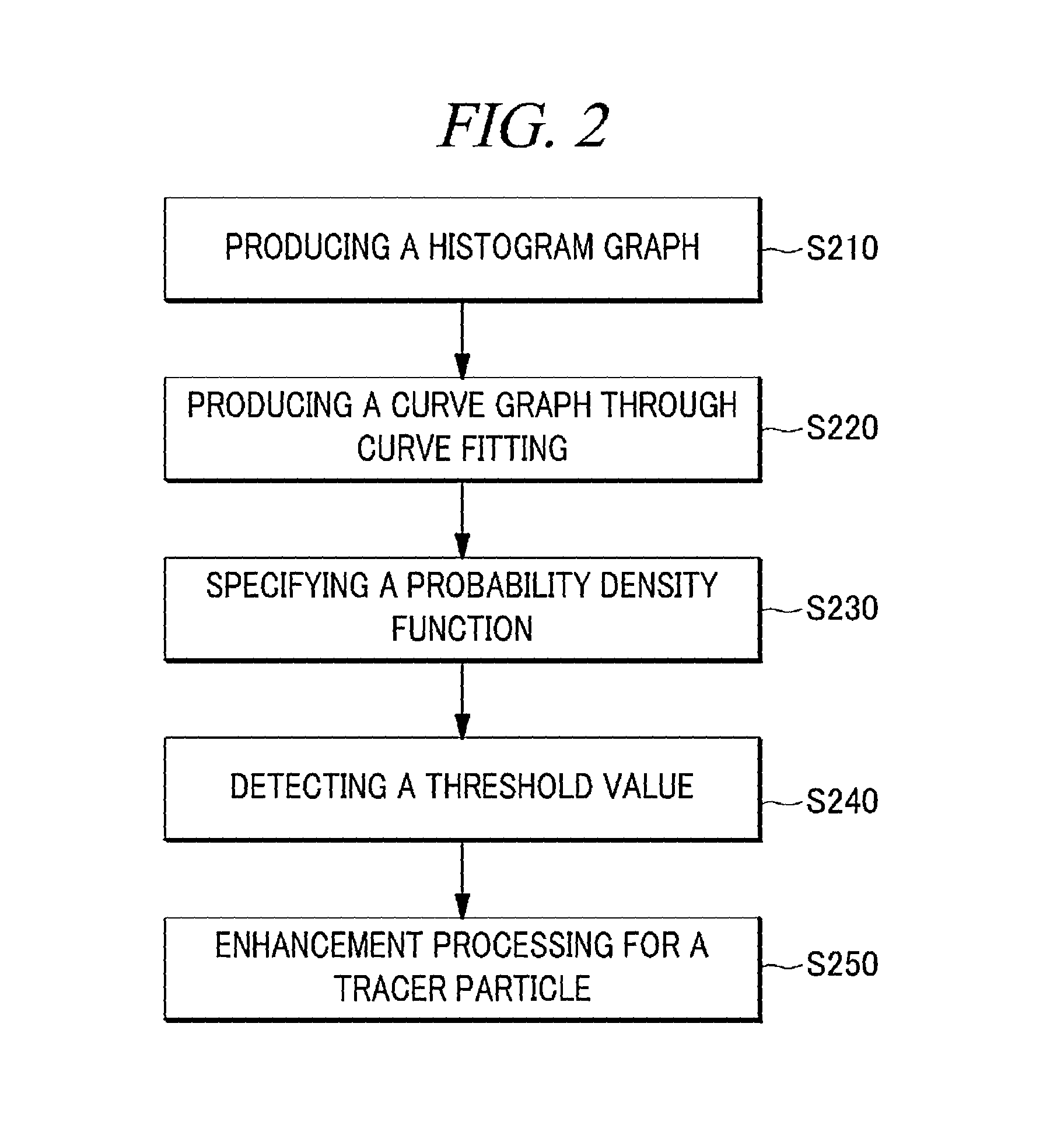
[0021]In accordance with the example embodiments, the dynamic variation calculating device can more exactly calculate dynamic variation of an object, by using displacement of a tracer particle between different two (2) images. That is, in a relation between a tracer particle included in an image, which is a reference for velocity calculation, and a peripheral image, the dynamic variation calculating device can clearly calculate displacement of a tracer particle in different two (2) images, through enhancement processing that sets brightness of the tracer particle to reference brightness or higher.

Problems solved by technology

However, there may be the case where it is difficult to exactly measure velocity of fluid depending on an environment where the PIV method is used, e.g., characteristics of the fluid.
For example, there may be difficulty in measuring blood flow velocity within the left ventricle by using the echo PIV device.
That is, if any tissue of the left ventricle radiates an echo signal having similar intensity to that of the tracer particle, it is difficult to clearly discriminate an acquired ultrasonic image, and there may be the possibility that an error will occur in measuring the velocity.

Method used


Image

  • Device and method for calculating dynamic variation of object
  • Device and method for calculating dynamic variation of object
  • Device and method for calculating dynamic variation of object

Examples


Embodiment Construction

[0028]Hereinafter, example embodiments will be described in detail with reference to the accompanying drawings so that inventive concept may be readily implemented by those skilled in the art. However, it is to be noted that the present disclosure is not limited to the example embodiments, but can be realized in various other ways. In the drawings, certain parts not directly relevant to the description are omitted to enhance the clarity of the drawings, and like reference numerals denote like parts throughout the whole document.

[0029]Throughout the whole document, the terms “connected to” or “coupled to” are used to designate a connection or coupling of one element to another element and include both a case where an element is “directly connected or coupled to” another element and a case where an element is “electronically connected or coupled to” another element via still another element. Further, the term “comprises or includes” and / or “comprising or including” means that one or m...


PUM


Abstract

There is provided a device for calculating dynamic variation of an object, comprising: an enhancement processing unit that adjusts brightness of a pixel determined to indicate a particle dispersed in the object in at least two (2) images generated for the object at different time points; and a calculating unit that calculates dynamic variation of the object based on correlation of the different two (2) images processed by the enhancement processing unit. Herein, the enhancement processing unit sets brightness of a pixel having brightness with a threshold value or higher for each of the images to reference brightness higher than the threshold value.

Description

CROSS-REFERENCE TO RELATED APPLICATION[0001]This application claims the benefit of Korean Patent Application No. 10-2012-0115644 filed on Oct. 17, 2012 and PCT Application No. PCT / KR2013 / 000062 filed on Jan. 4, 2013, the entire disclosures of which are incorporated herein by reference.TECHNICAL FIELD[0002]The embodiments described herein pertain generally to a device and a method for calculating dynamic variation of an object.BACKGROUND ART[0003]In recent, there has been known a technology that measures and visualizes velocity of fluid by using a particle image velocimetry (PIV) method. A PIV device visually represents flow of fluid, and is a technology that can measure, for example, instantaneous velocity of a tracer particle in a cross section of fluid. In this case, a tracer particle is dispersed in fluid, which is an object for velocity measurement, and a size of the tracer particle is small enough to sufficiently follow flow of the fluid. Meanwhile, the technology applied to th...

Claims


Application Information

Patent Timeline
Patent Type & Authority Patents(United States)
IPC IPC(8): G06T5/00G06T7/20
CPCG06T7/2013G06T5/007G06T2207/20056G06T2207/10004G06T2207/10028G06T7/223A61B5/00G06T5/00G06T7/20
Inventor MOON, YOUNG JUNESONG, YONGNAMPARK, SEUNG WOOALI, ZAMIRI
Owner KOREA UNIV RES & BUSINESS FOUND
Learn More