Electromagnet device and electromagnetic relay using the same

a technology of electromagnetic relay and electromagnetic device, which is applied in the direction of electrical apparatus, coils, and electromagnet relay details, can solve the problems of hardly performing work to tie up the lead wire of the coil, the tying-up portion of the coil terminal cannot be expanded, etc., and achieves advantageously high space efficiency and eliminates dead space

Active Publication Date: 2016-09-06
ORMON CORP
View PDF42 Cites 6 Cited by
  • Summary
  • Abstract
  • Description
  • Claims
  • Application Information

AI Technical Summary

Benefits of technology

[0007]One or more embodiments of the present invention provides an electromagnet device in which the work to tie up the lead wire of the coil is easily performed even if the adjacent coil terminals are close to each other.
[0020]Accordingly, the tying-up portion may be folded after the lead wire of the coil is tied up to the tying-up portion of the coil terminal projected from the guard portion of the spool. The tying-up work is more easily performed than ever before, and the dead space is eliminated. Therefore, the electromagnet device having the high space efficiency is advantageously obtained.

Problems solved by technology

However, because the adjacent coil terminals are close to each other in the coil block, unfortunately the tying-up portion of the coil terminal cannot be enlarged, but work to tie up the lead wire of the coil is hardly performed.

Method used


Image

  • Electromagnet device and electromagnetic relay using the same
  • Electromagnet device and electromagnetic relay using the same
  • Electromagnet device and electromagnetic relay using the same

Examples


Embodiment Construction

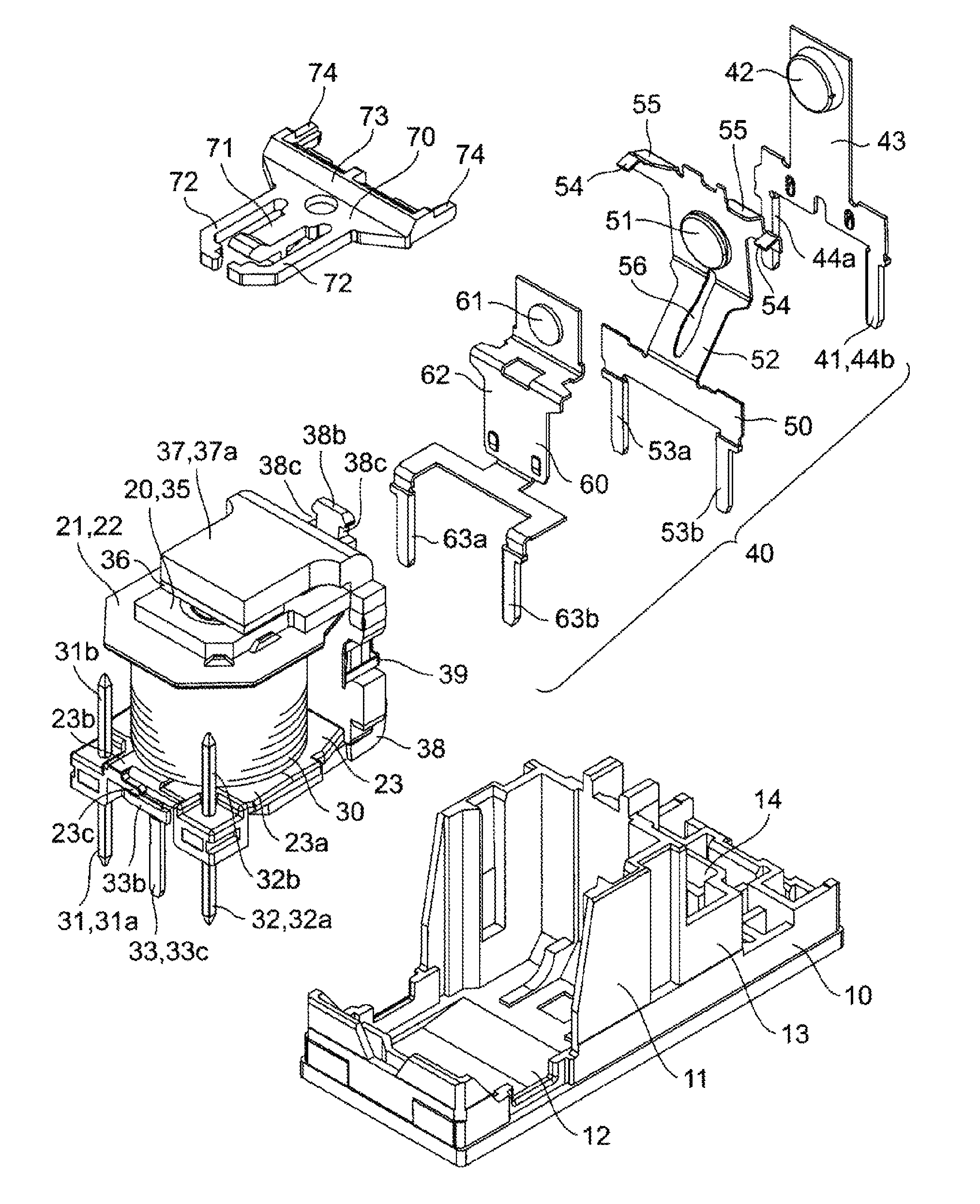
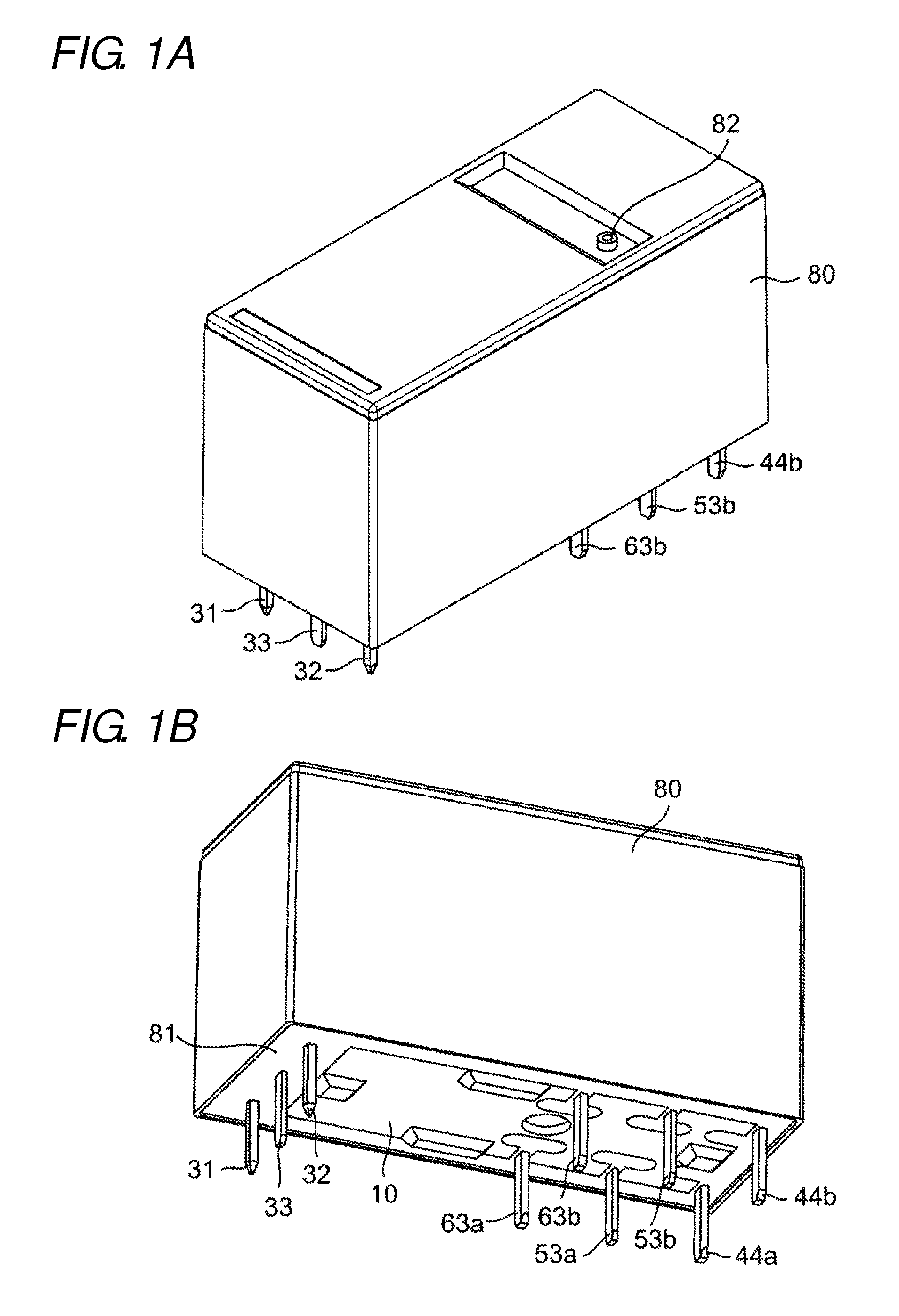
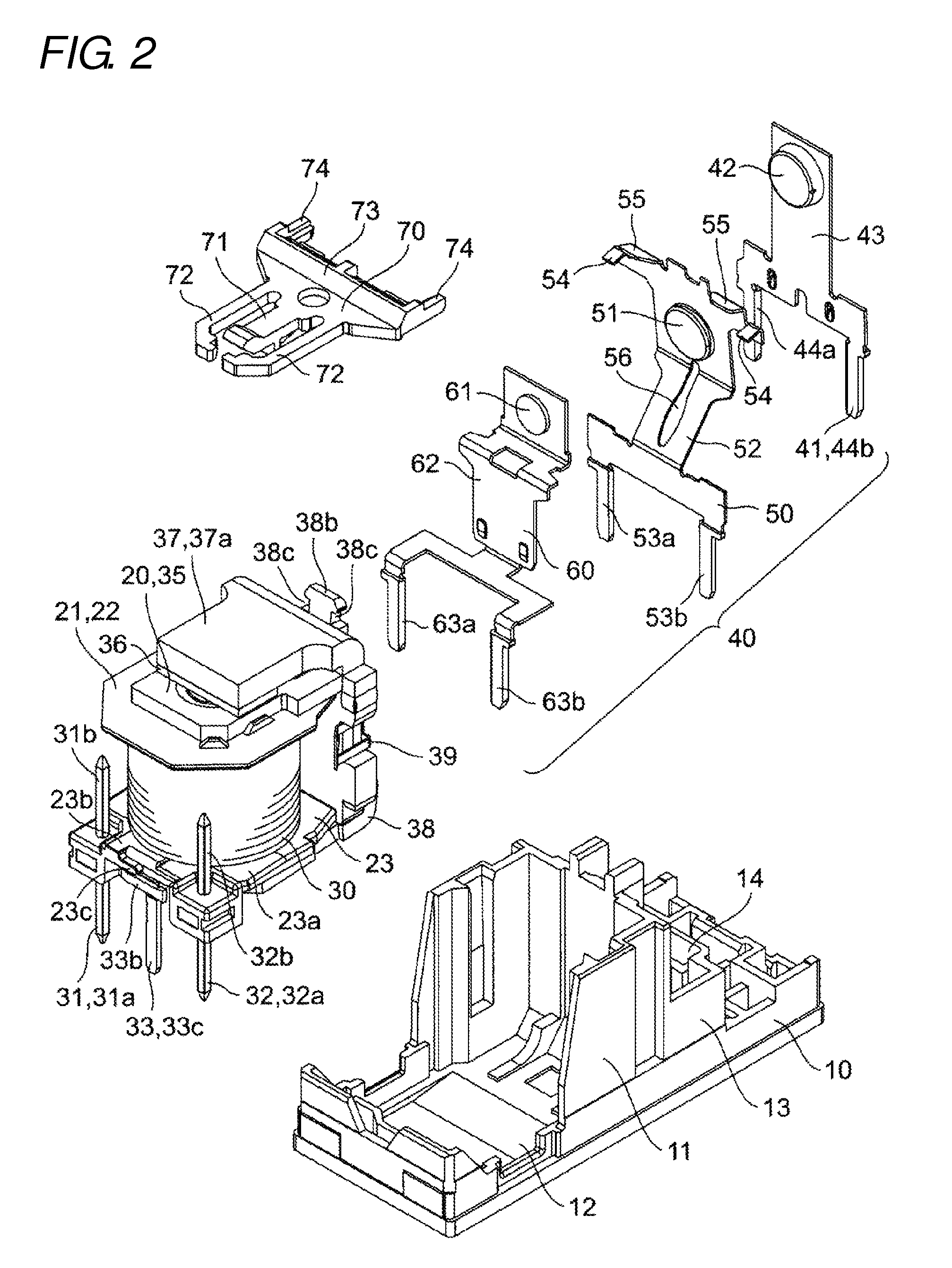
[0029]Embodiments of the present invention will be described with reference to the drawings. In embodiments of the invention, numerous specific details are set forth in order to provide a more thorough understanding of the invention. However, it will be apparent to one of ordinary skill in the art that the invention may be practiced without these specific details. In other instances, well-known features have not been described in detail to avoid obscuring the invention. A self-holding electromagnetic relay to which an electromagnet device according to one or more embodiments of the present invention is applied will be described with reference to FIGS. 1A to 8.

[0030]In the following description, a term (such as terms including “up”, “down”, “side”, and “end”) indicating a specific direction or position is used as needed basis. However, the use of the term is aimed only at easy understanding of one or more embodiments of the present invention with reference to the accompanying drawing...


PUM

PropertyMeasurementUnit
widthaaaaaaaaaa
tensile forceaaaaaaaaaa
shapeaaaaaaaaaa

Abstract

An electromagnet device has a spool having a guard portion at at least one end thereof, a coil wound around a body portion of the spool, and a coil terminal press-fitted in the guard portion. A lead wire of the coil is tied up to a tying-up portion of the coil terminal projected from the guard portion. The tying-up portion is folded toward the guard portion of the spool after the lead wire of the coil is tied up to the tying-up portion of the coil terminal extending in a direction receding from the spool.

Description

BACKGROUND[0001]1. Field[0002]The present invention relates to an electromagnet device, particularly to a coil terminal attaching structure.[0003]2. Related Art[0004]Conventionally, as to the electromagnet device, for example, Japanese Unexamined Patent Publication No. 2005-183554 discloses a coil block including a coil bobbin, a coil formed by winding a coil wire around the coil bobbin, and at least three coil terminals to which the coil wire is connected, the coil terminals being projected in substantially parallel toward the same direction from a base of the coil bobbin. In the coil block, a part of an inner coil terminal of the coil terminals projected in parallel is bent and raised near the base to form a projection having a shape accommodated in a width in a direction orthogonal to an extending direction of the coil terminals, and the coil wire is welded to the projection while tied up to the projection.[0005]In the coil block, as illustrated in FIGS. 5 to 7 of Japanese Unexam...

Claims


Application Information

Patent Timeline
Patent Type & Authority Patents(United States)
IPC IPC(8): H01H51/22H01H50/44H01F5/04
CPCH01H50/443H01F5/04H01H2050/446
Inventor KATO, TATSUROYAMAMOTO, MASAAKIMURAKAMI, KAZUYATSUJIKAWA, KAZUKINARIMATSU, DAISUKEMATSUO, SHINYAKITAGUCHI, HARUMICHISUMINO, TOSHIFUMI
Owner ORMON CORP
Why Eureka
Try Eureka