Track structure capable of supplying power

a technology of track structure and power supply, applied in the direction of electrical cable installation, cable arrangement between relatively moving parts, coupling device connection, etc., can solve the problems of inability to use flexible fpds, laborious power cord replacement, and limited disassembly locations of track structur

Active Publication Date: 2016-09-13
AOPEN
View PDF8 Cites 6 Cited by
  • Summary
  • Abstract
  • Description
  • Claims
  • Application Information

AI Technical Summary

Benefits of technology

[0004]Accordingly, the present disclosure provides a track structure capable of supplying power, which is provided for disposing slidably at least an electronic device. As the electronic device slides on the track structure, the track structure can supply power continuously to the electronic device, so that the electronic device can acquire power without connecting to a socket through a power cord. Thereby, the electronic device will not be limited by the length of the power cord and the location of the socket; it can be moved to the desired location according to a user's requirement.

Problems solved by technology

Although FPDs can be disposed at any positions through the above mechanisms, their disposition locations are still limited; they have to be disposed near sockets.
It is tedious to change the power cords.
Hence, the FPDs cannot be used with flexibility due to the limits in the lengths of power cords.

Method used


Image

  • Track structure capable of supplying power
  • Track structure capable of supplying power
  • Track structure capable of supplying power

Examples


first embodiment

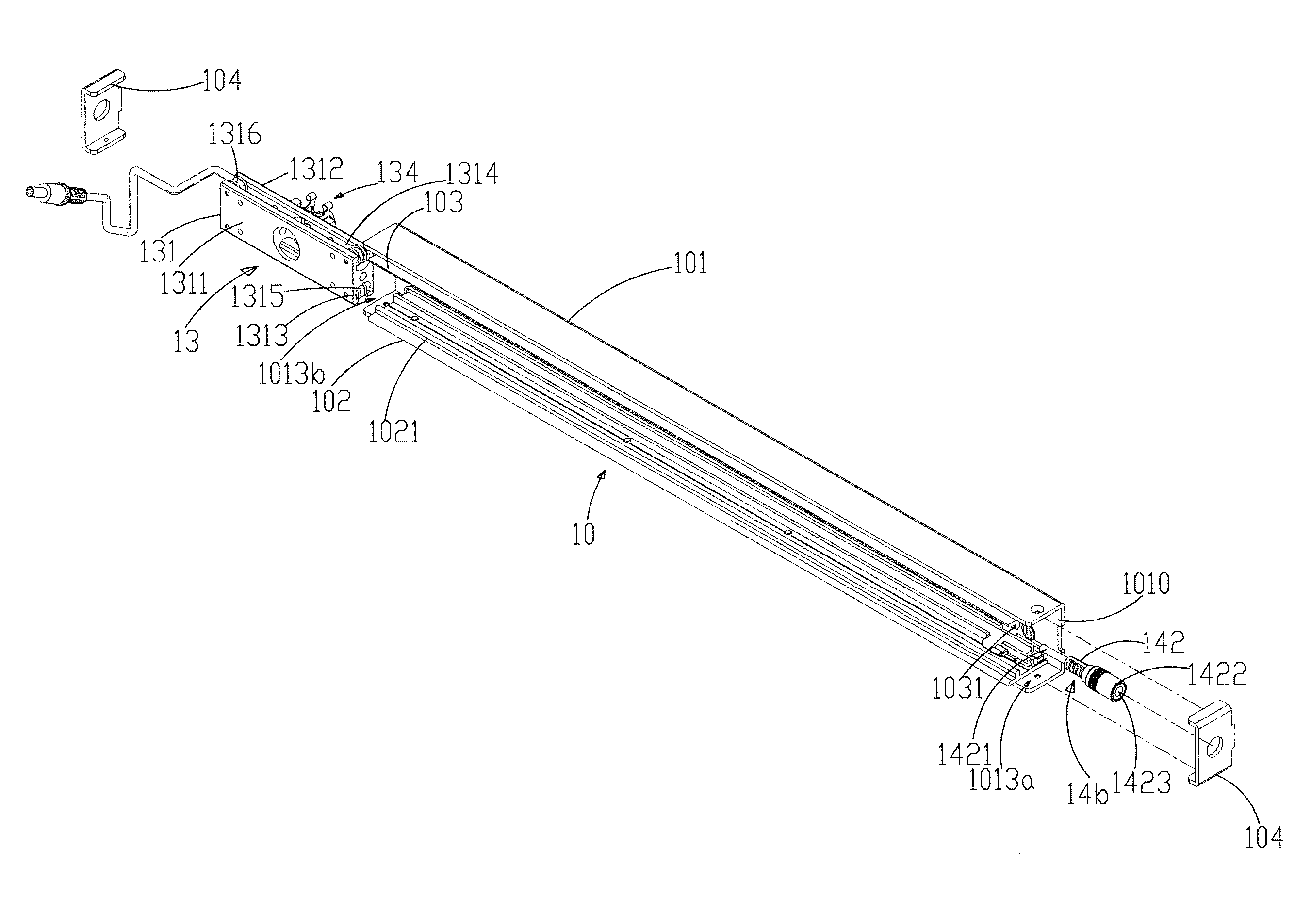
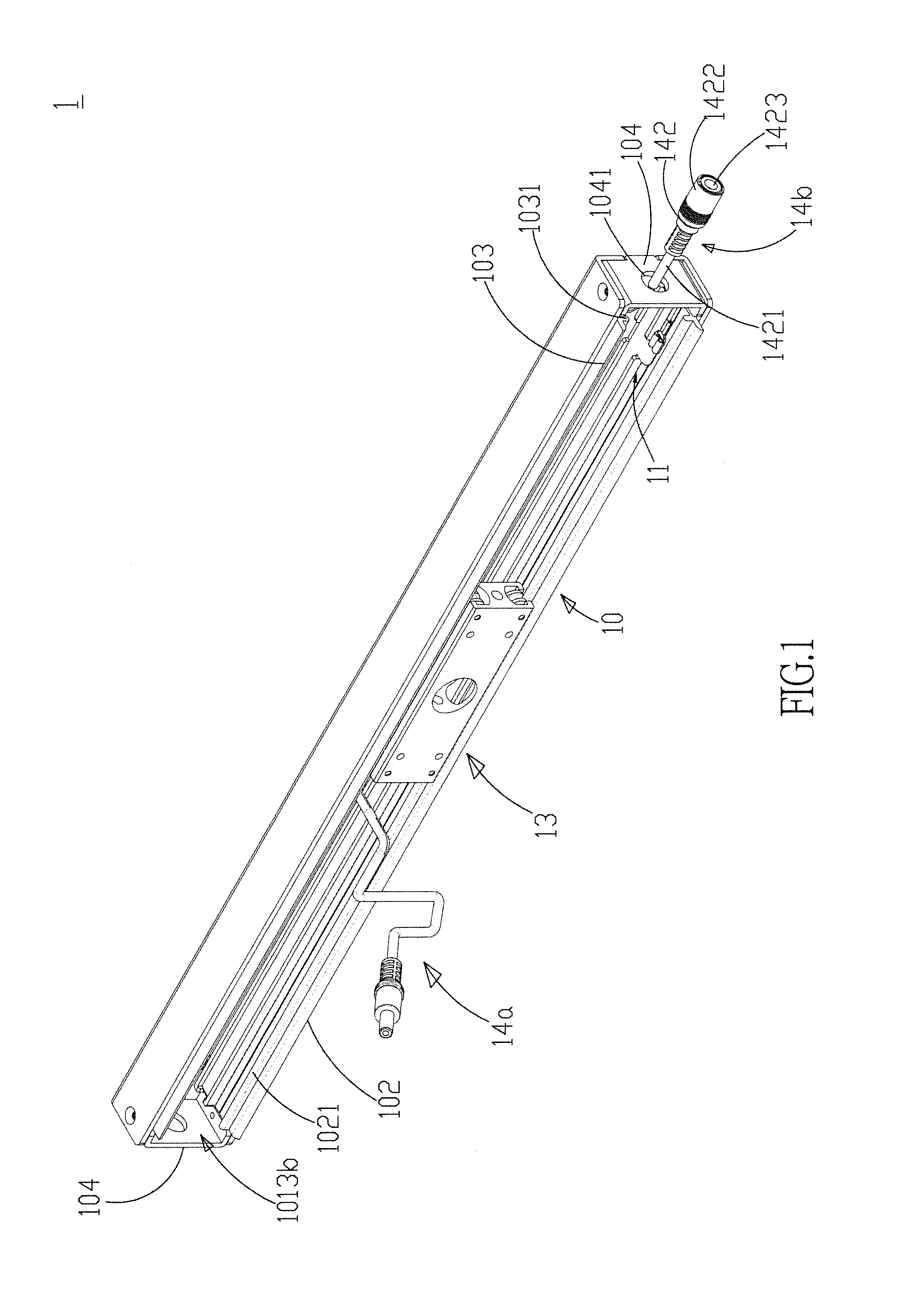
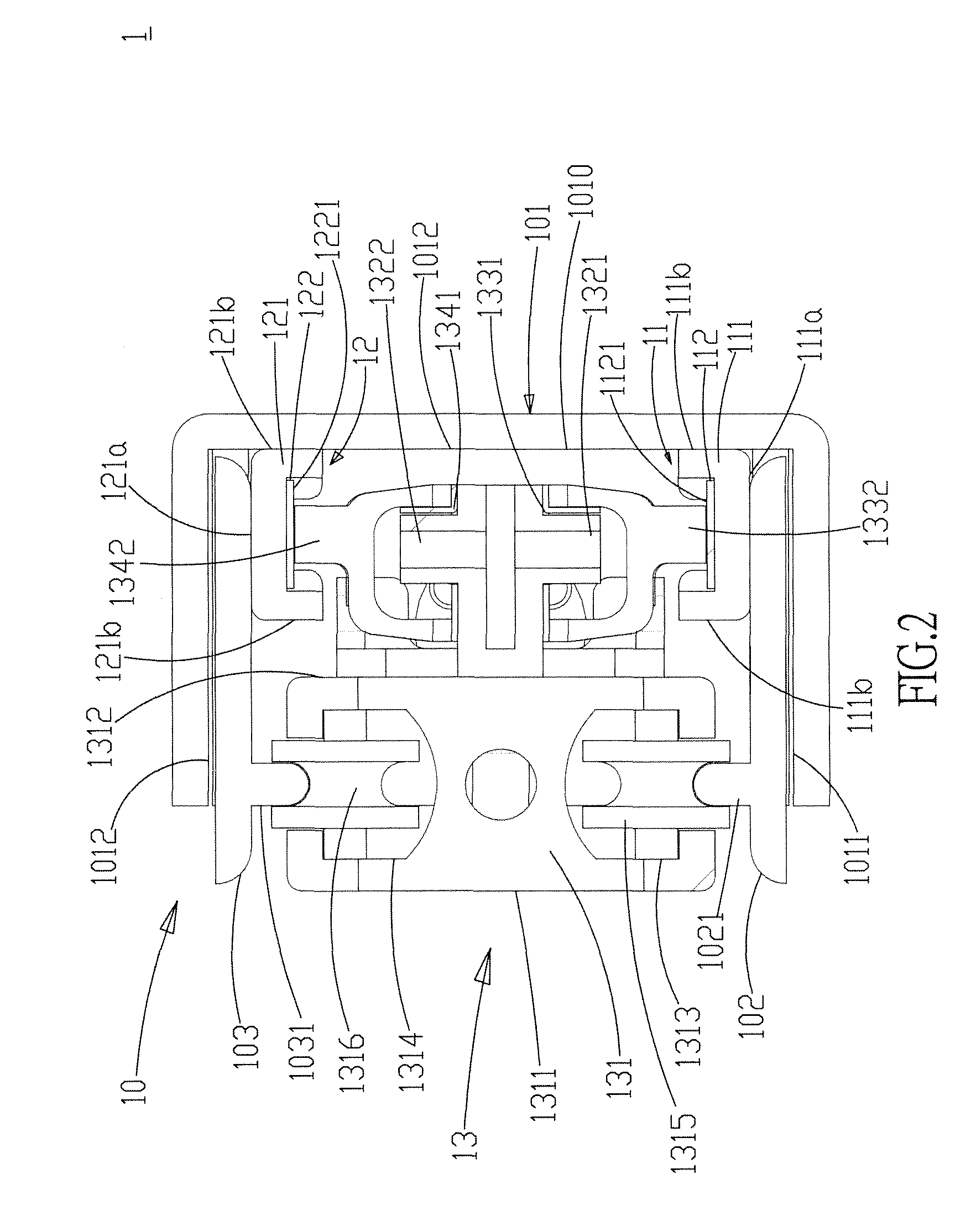
[0021]FIGS. 1 to 3 show an exterior view and a cross-sectional view of the track structure and an assembly view of the track module, the first conducting module, and the second conducting module according to the present disclosure. As shown in the figures, the present embodiment provides a track structure 1 capable of supply power. The track structure 1 comprises a track module 10, a first conducting module 11, a second conducting module 12, a sliding module 13, a first electrical transmission module 14a, and a second electrical transmission module 14b. The track module 10 comprises a track accommodating base 101, a first track 102, and a second track 103. The track accommodating base 101 has a bottom part 1010, a first sidewall 1011, and a second sidewall 1012. The first and second sidewalls 1011, 1012 are disposed on both sides of the bottom part 1010, respectively, and thus making the track accommodating base 101 U-shaped. The track accommodating base 101 has a first gap 1013a an...

second embodiment

[0035]FIG. 8 shows a usage status diagram of the track structure according to the present disclosure. As shown in the figure, there is only one electronic device disposed at the track structure 1 according to the previous embodiment. The track structure 1 according to the present embodiment connects a first electronic device 2a and a second electronic device 2b in series. Accordingly, the track structure 1 according to the present embodiment has a first sliding module 13a and a second sliding module 13b sliding on the sliding module 10. The first electronic device 2a is disposed at the first sliding module 13a; the second electronic device 2b is disposed at the second sliding module 13b. Then, the power supply 17, the first conducting module 11, the first electrode of the first sliding module 13a, the first electronic device 2a, the second electrode of the first sliding module 13a, and the second conductive module (as the second conductive module 12 shown in FIG. 1) form a first con...


PUM


Abstract

The present disclosure relates to a track structure capable of supplying power, which comprises a track module, a first conducting module, a second conducting module, at least a sliding module, a first electrical transmission module, and a second electrical transmission module. Each track module is provided for disposing an electronic device. The electronic device slides along the track module via the sliding module. The first electrical transmission module is connected to the electronic device, and a first electrode and a second electrode of the sliding module. The first and second electrodes contact the first and second conducting modules, respectively. The second electrical transmission module is connected to the first and second conducing modules and connected to a power supply. The power supply supplies power and transmit the power to the electronic device through the track structure.

Description

FIELD OF THE DISCLOSURE[0001]The present disclosure relates generally to a track structure, and particularly to a track structure for disposing slidably an electronic device and capable of supplying power to the electronic device continuously.BACKGROUND OF THE DISCLOSURE[0002]Thanks to the progresses in technologies, flat-panel displays (FPDs) have almost replaced completely cathode ray tube (CRT) displays and become the mainstream in modern display technologies. Compared with the bulky size of traditional CRT displays, FPDs have the advantages of low power consumption, low radiation, and thin outlines. In addition, the expansion in the size of FPDs also popularizes thin digital TVs in consumer and entertainment applications such as home viewing, outdoor advertisements, and exhibition purposes.[0003]Currently, FPDs are mostly mounted on walls using frames. They can be disposed on tables or ground using tripods. Alternatively, they can be hung on ceilings using arm holders. Although ...

Claims


Application Information

Patent Timeline
Patent Type & Authority Patents(United States)
IPC IPC(8): H02G11/00F16M11/42F16M13/02H01R25/14H02G3/10
CPCH02G11/00F16M11/425F16M13/02H01R25/142H02G3/105
Inventor CHEN, YI-JEN
Owner AOPEN
Why Eureka
Try Eureka