Printing device, and control method of a printing device

a printing device and control method technology, applied in transportation and packaging, electrochemical generators, secondary cells servicing/maintenance, etc., can solve the problems of adversely affecting the printing operation, inability to supply the power required for printing operation, etc., and achieve the effect of suppressing the power consumption of printing operation

a printing device and control method technology, applied in transportation and packaging, electrochemical generators, secondary cells servicing/maintenance, etc., can solve the problems of adversely affecting the printing operation, inability to supply the power required for printing operation, etc., and achieve the effect of suppressing the power consumption of printing operation

US20170368853A1Active Publication Date: 2017-12-28SEIKO EPSON CORP

Image

  • Printing device, and control method of a printing device
  • Printing device, and control method of a printing device
  • Printing device, and control method of a printing device

Examples


Embodiment Construction

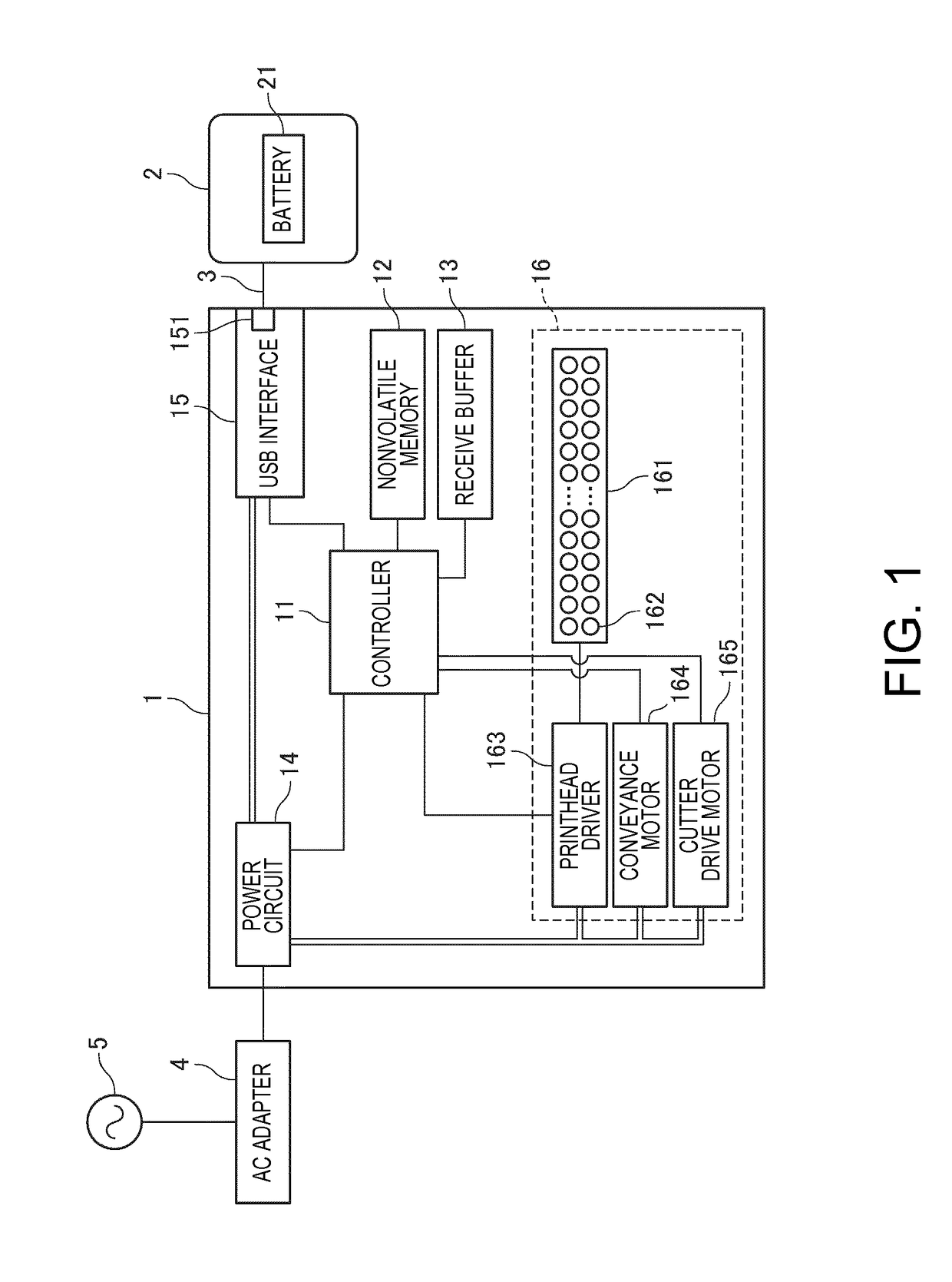
[0027]FIG. 1 is a block diagram illustrating the configuration of a printer 1 (printing device).

[0028]The printer 1 is a device that prints text and images, for example, on recording media based on data input from a connected external device. In this embodiment of the invention, the printer 1 connects to a smart device 2 (external device), and based on data input from the smart device 2 prints text, images or other content on recording media. The printer 1 internally stores thermal roll paper (not shown in the figure) as the recording medium, and prints text and images by applying heat to the recording surface of the thermal roll paper by means of a thermal line head 161 (printhead) having multiple resistors 162 as heat elements.

[0029]The printer 1 operates using power supplied from an AC adapter 4 that connects to a commercial power source 5.

[0030]The smart device 2 is a smartphone, tablet, or other mobile terminal that can be easily carried around by the user. As shown in FIG. 1, ...


PUM

PropertyMeasurementUnit
timeaaaaaaaaaa
poweraaaaaaaaaa
timeaaaaaaaaaa

Abstract

Power required for a printing operation can be supplied while supplying power to a connected external device. A printer 1 connects to a smart device 2, and has: a power circuit 14; a USB interface 15 capable of supplying power to the smart device while communicating by wire with the smart device 2; a print unit 16 that prints; and a controller 11 that controls the print unit 16 to print in a power conservation mode when information instructing printing by the print unit 16 is received by the interface 15 from the smart device 2 while supplying power from the power circuit 14 to the smart device 2.

Description

[0001]This application claims priority under 35 U.S.C. ยง119 to Japanese Patent Application No. 2016-123300 filed on Jun. 22, 2016, the entire disclosure of which is expressly incorporated by reference herein.BACKGROUND1. Technical Field[0002]The present invention relates to a printing device, and a control method of a printing device.2. Related Art[0003]Devices that control the supply of power to a connected external device are known from the literature. See, for example, JP-A-2015-176442.[0004]JP-A-2015-176442 describes an image processing device configured to report, to a connected peripheral device, when a state of the image processing device changes, combinations of the voltage and current of the power that can be supplied to the connected peripheral device, and if the voltage and current combination required by the peripheral device is included in the reported combinations, supply power of the voltage and current the peripheral device requires.[0005]When an external device is c...

Claims


Application Information

Patent Timeline
28 Dec 2017
Publication
US20170368853A1
IPC
B41J23/00; H01M10/44; B41J2/32; H01M10/0525; H02J7/02; H01M10/48
CPC
B41J23/00; B41J2/32; H02J7/02; H01M10/48; H01M10/44; H01M10/0525; B41J2/35; B41J29/393
Inventors
SATAKE, EIJI