Controller for power converter

a power converter and control board technology, applied in the direction of power conversion systems, ac-ac conversion, electrical apparatus, etc., can solve the problems of reducing the efficiency and reliability of the device, the magnitude of the ripple, etc., to reduce undesirable magnetostrictive noise, reduce the magnitude of the frequency spectrum peak, and prevent damage or the like to the power converter

Active Publication Date: 2016-10-20
FUJI ELECTRIC CO LTD
View PDF9 Cites 7 Cited by
  • Summary
  • Abstract
  • Description
  • Claims
  • Application Information

AI Technical Summary

Benefits of technology

[0031]Furthermore, as illustrated in FIG. 10, when an FFT analysis is performed on the reactor currents that include these ripple components, the resulting spectrum exhibits peaks near integer multiples of the carrier frequency. In principle, randomly modulating the carrier frequency to reduce the ripple components as disclosed in Patent Document 2 and spread out the spectrum should make it possible to reduce the magnetostrictive noise.
[0032]However, while although randomly changing the carrier frequency makes it possible to spread out the spectrum, in some cases unexpected frequencies may increase the magnitude of the ripple components, thereby decreasing the efficiency and reliability of the device.
[0035]Therefore, one of the problems to be solved by the present invention is to provide a controller that makes it possible to normalize the ripple components in the reactor currents in order to spread out the frequencies in the frequency spectrum and also makes it possible to decrease the magnitude of peaks in the frequency spectrum in order to reduce magnetostrictive noise.
[0036]Another problem to be solved by the present invention is to provide a controller that makes it possible to supply power to a load without causing a circulating current even when using a plurality of power converters connected together in parallel.
[0045]The present invention, in at least one aspect, makes it possible to normalize the ripple components in the reactor currents across the entire phase angle range in order to spread out the frequencies in the reactor current frequency spectrum and also makes it possible to decrease the magnitude of peaks in the frequency spectrum in order to reduce undesirable magnetostrictive noise.
[0046]Moreover, in at least one aspect of the present invention, when using a plurality of power converters connected together in parallel, the carrier frequencies are changed according to a common phase reference signal, thereby making it possible to synchronize the power converter carriers and prevent circulating currents as well as to prevent damage or the like to the power converters.

Problems solved by technology

However, while although randomly changing the carrier frequency makes it possible to spread out the spectrum, in some cases unexpected frequencies may increase the magnitude of the ripple components, thereby decreasing the efficiency and reliability of the device.
Moreover, when the outputs of multiple power converters are connected together directly without using an isolation transformer like in the parallel connection system used for the uninterruptible power supplies 100A and 100B illustrated in FIG. 5, problems such as the following will occur if the carriers for each power converter are not synchronized.

Method used


Image

  • Controller for power converter
  • Controller for power converter
  • Controller for power converter

Examples


Embodiment Construction

[0059]Next, an embodiment of the present invention will be described with reference to figures.

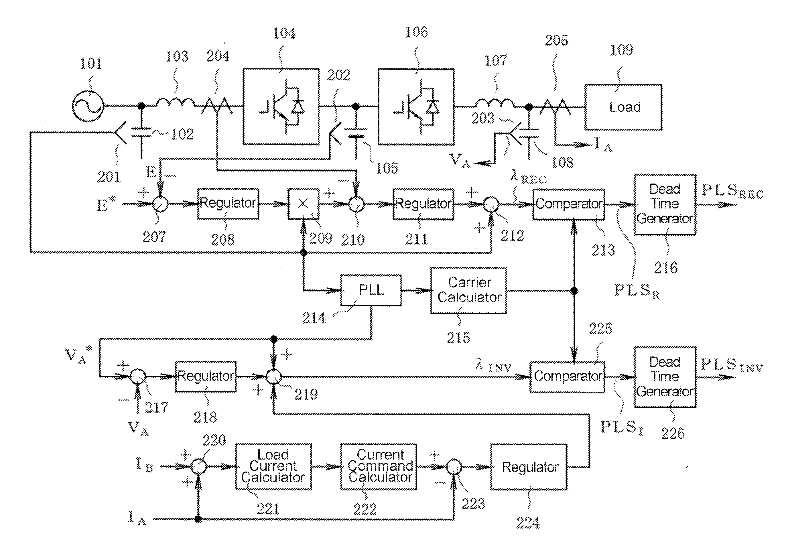
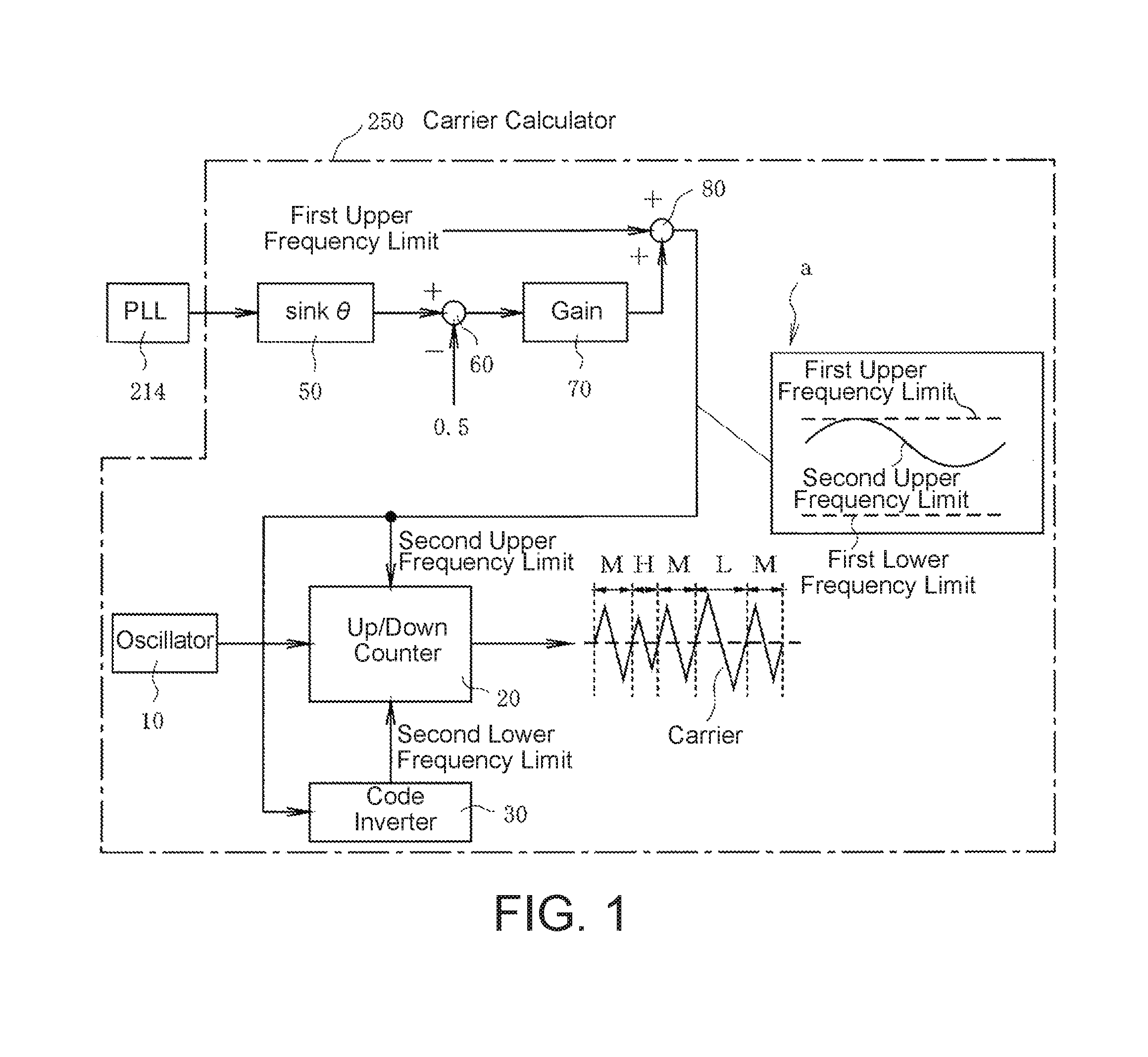
[0060]FIG. 1 is a block diagram illustrating a configuration of a carrier calculating unit 250 in a controller according to this embodiment. Note that the overall configuration of the controller is the same as in FIG. 6 except in that the present controller is configured by replacing the carrier calculating unit 215 illustrated in FIG. 6 with the carrier calculating unit 250 illustrated in FIG. 1.

[0061]Moreover, the power converter to be controlled is an uninterruptible power supply that includes a rectifier converter 104 connected via a battery 105 to an inverter converter 106 (as illustrated in FIG. 6) and can convert AC power to DC power and then back to AC power.

[0062]As illustrated in FIG. 1, a phase reference signal output from a PLL circuit 214 is input to a sine wave calculating unit 50. The sine wave calculating unit 50 calculates a sine wave sinkθ in which when the inverter conve...


PUM


Abstract

The present disclosure provides a controller for a power converter that converts input power to a prescribed form and outputs the power by switching a semiconductor switching device ON and OFF and that has an output circuit including a filtering reactor on an output side, the controller including: a carrier calculating unit that generates a carrier having prescribed frequencies for generating a control signal that switches the semiconductor switching device ON and OFF, wherein the carrier calculating unit generates the carrier such that a carrier frequency at phase angles where ripple components in a current flowing through the reactor are relatively high in magnitude, which is defined as a high ripple carrier frequency, is higher than a carrier frequency at phase angles where the ripple components are relatively low in magnitude, which is defined as a low ripple carrier frequency.

Description

BACKGROUND OF THE INVENTION[0001]1. Technical Field[0002]The present invention relates to a controller for a power converter in which an output unit includes a filtering reactor, the controller having an improved carrier generation scheme for obtaining control signals for semiconductor switching elements of the power converter.[0003]2. Background Art[0004]FIG. 5 illustrates a power converter in which two uninterruptible power supplies 100A and 100B are connected between a power system 101 and a load 109.[0005]Both uninterruptible power supplies 100A and 100B have the same configuration. Next, the configuration and operation of one of the uninterruptible power supplies 100A will be described.[0006]The uninterruptible power supply 100A converts AC power from the power system 101 to DC power using a rectifier and uses that DC power to charge a battery. The DC power from the battery is then converted back to AC power using an inverter and supplied to a load 109.[0007]The rectifier inclu...

Claims


Application Information

Patent Timeline
Patent Type & Authority Applications(United States)
IPC IPC(8): H02M7/217
CPCH02M2005/2932H02M7/2173H02M1/12H02M1/126H02M5/4585H02M1/123
Inventor FUJII, KANSUKE
Owner FUJI ELECTRIC CO LTD
Why Eureka
Try Eureka