
Wireless power supply device and method

a power supply device and wireless technology, applied in the field of electrical devices, can solve the problems of increasing the space occupied by the transmitter and the user's expenditure, the inability to receive the power supplied from the transmitter, and the increase in the difficulty of installation and deployment of the apparatus, so as to reduce the space occupied by the transmitter and the expenditur

Inactive Publication Date: 2013-12-26
HAIER GRP CORP +1
View PDF8 Cites 6 Cited by
  • Summary
  • Abstract
  • Description
  • Claims
  • Application Information

AI Technical Summary

Benefits of technology

The present invention proposes a wireless power supplying device and method that can effectively reduce the number of transmitters, supply power to one or more different receivers by using the same transmitter, and reduce the space occupied by the transmitters and the expenditure for purchasing the transmitters. It simplifies the installation, deployment, and usage of the apparatus, while providing reasonably power to the receivers. The control circuit can determine the power required by each transmitting part and individually supply power to the coil of each transmitting part based on the determination result, ensuring the proper operation of each receiver. This reduces the number and complexity of the transmitting parts, and simplifies the installation, deployment, and usage of the apparatus.

Problems solved by technology

However, for a tailless computer with power of 100 W, it cannot receive the power supplied from the transmitter due to the mismatch of power.
Thus, both the space occupied by the transmitters and the user's expenditure will increase.
Further, since the user needs to arrange a plurality of transmitters, the difficulty of installation and deployment of the apparatus is increased, and it is inconvenient for the user to use the apparatus.
The solution of supplying power to a plurality of receivers in a wireless manner in the related technologies is defective, because excessive space is occupied by a plurality of transmitters that are required, the user's expenditure is increased, and the installation, deployment and usage of the apparatus are inconvenient.
However, an effective solution has not been proposed to overcome the above defects.

Method used


Image

  • Wireless power supply device and method
  • Wireless power supply device and method
  • Wireless power supply device and method

Examples


Embodiment Construction

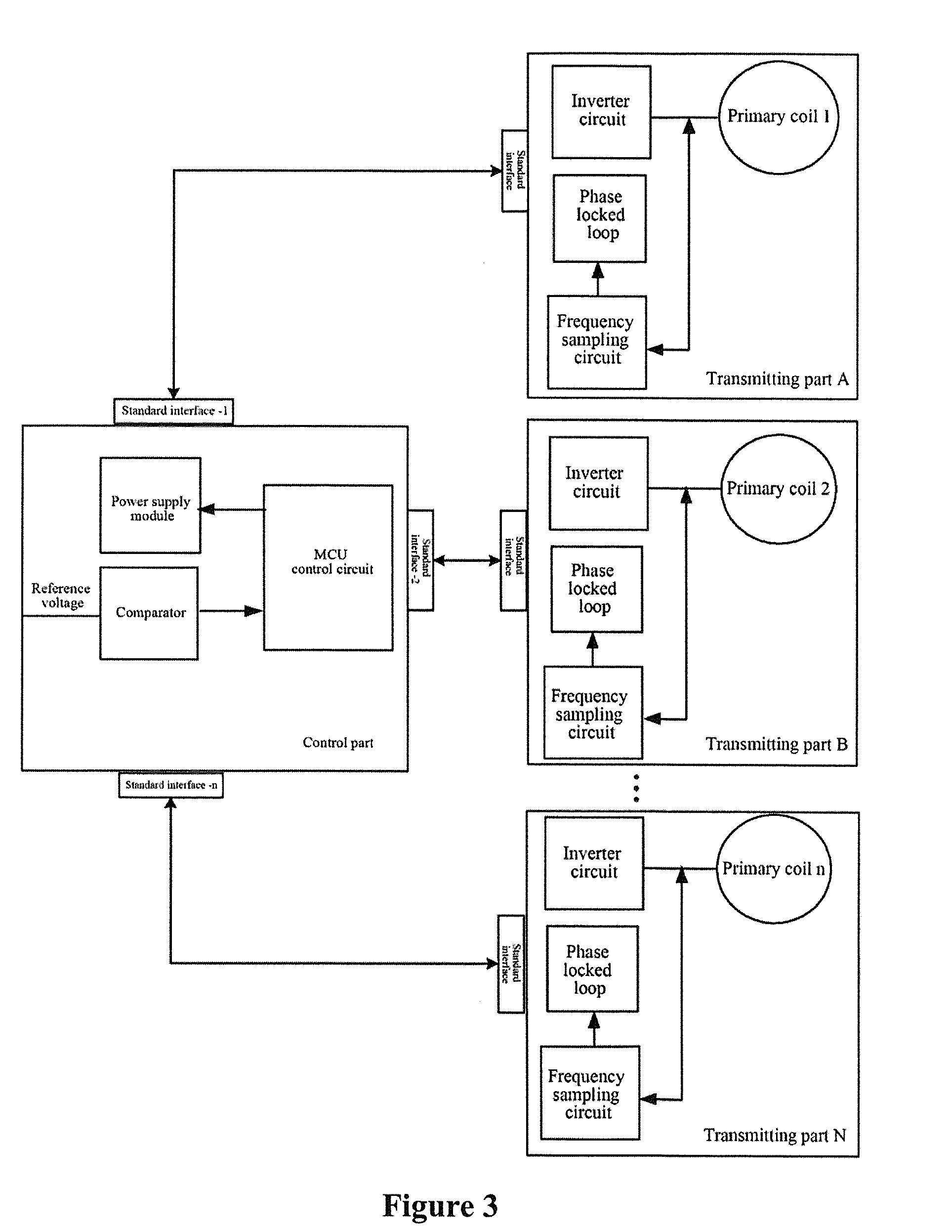
[0037]In view of problems in the related art that excessive space is occupied by the transmitters of the wireless power supplying device, the user's expenditure is increased, and the installation, deployment and usage of the device are inconvenient, the present invention proposes an architecture in which a control part and a transmitting part are separated, so that a control circuit can determine the power required for at least one transmitting part connected to the control part and individually supply power to the coil of each connected transmitting part, thereby enabling each coil to generate electromagnetic induction with the desired power, and achieving the reasonable power supplying to each receiver and allowing the receiver to operate properly.

[0038]A specific implementation of the present invention will be described in detail below in conjunction with the accompanying drawings.

[0039]According to an embodiment of the present invention, there is provided a wireless power supply...


PUM


Abstract

There is provided a wireless power supplying device and method. The device includes a control part and at least one transmitting part connected with the control part. The control part includes a control circuit and a power supply module. The control circuit is used to determine the power requirement of the transmitting part connected with the control part and control the power supply module to transmit an electrical signal satisfying the power requirement to the transmitting part. The transmitting part generates a magnetic field based on the electrical signal and supplies power to a load of a receiver. The wireless power supply device and method enable each coil to generate electromagnetic induction with desired power, to supply power for the receiver reasonably, and reduce the number and the complexity of the transmitting part.

Description

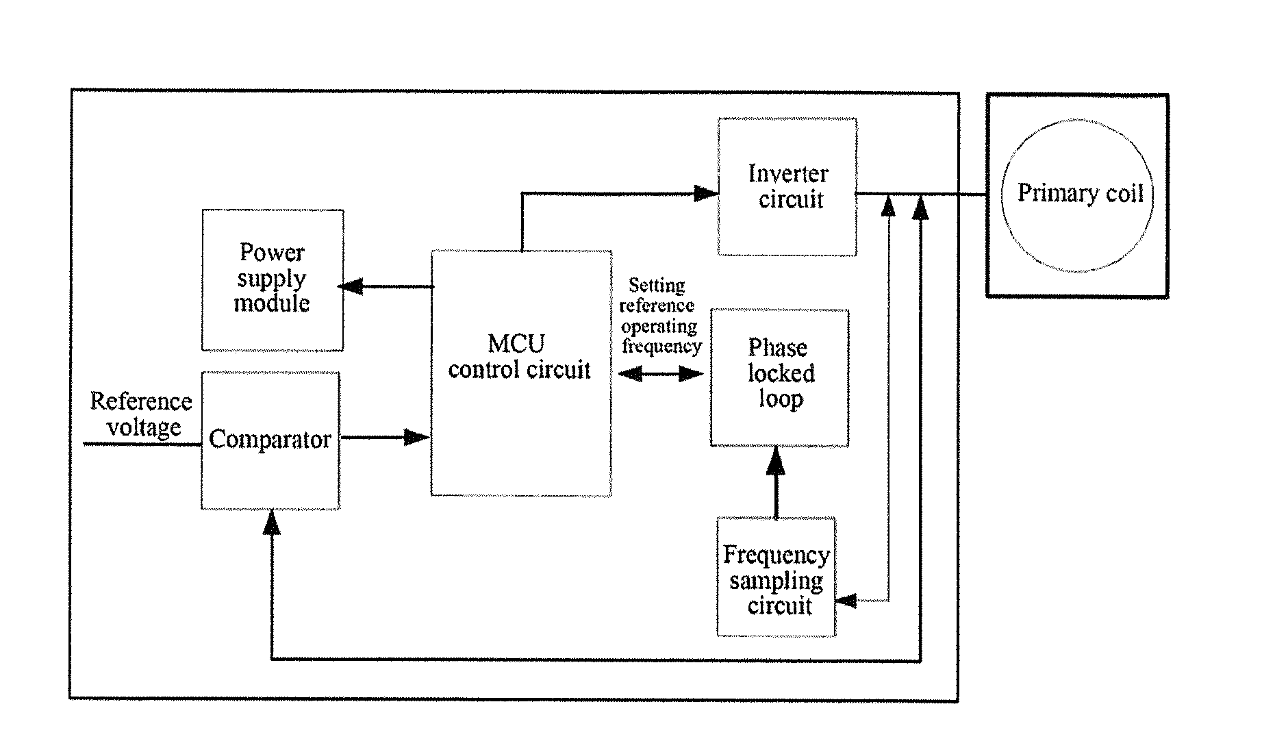
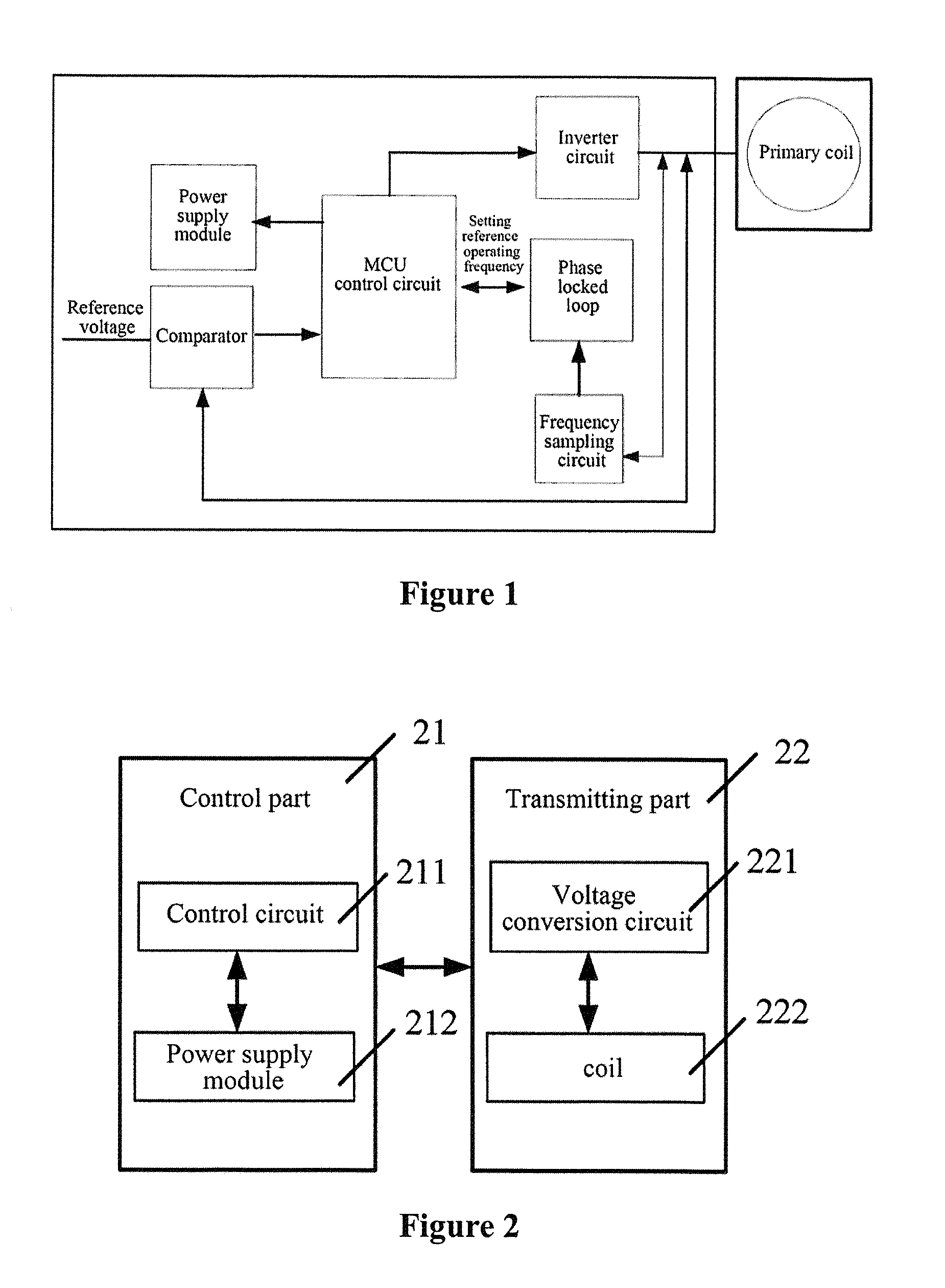
TECHNICAL FIELD[0001]The present invention relates to the field of electronics, and in particular, to a wireless power supplying device and method.TECHNICAL BACKGROUND[0002]In order to facilitate the use of an electrical apparatus by a user, a tailless product has been proposed by some manufacturers so far. The principle of the tailless product includes that: a transmitter of the product receives an external power supply (for example, the transmitter is connected to the mains supply voltage), and produce a corresponding magnetic field from an electrical signal through the electromagnetic conversion processing; and a receiver corresponding to the transmitter senses the generated magnetic field, converts the magnetic field into an electrical signal, and then provides the electrical signal to the load of the receiver.[0003]As shown in FIG. 1, the transmitter of the current tailless apparatus mainly includes: a power supply module, a comparator, a Microprogrammed Control Unit (MCU) cont...

Claims


Application Information

Patent Timeline
IPC IPC(8): H04B5/00
CPCH04B5/0037H04B5/0081H02J50/80H02J50/40H02J50/10H04B5/26H04B5/79
Inventor LI, DANDANG, YANGTAOSUN, HUIDIAO, DEPENGHUANG, XUETAOLIU, BAO
Owner HAIER GRP CORP
Learn More