Image transmission apparatus and recording medium

a technology of image transmission and recording medium, which is applied in the direction of digital output to print units, visual presentations, instruments, etc., can solve the problems of difficult inspection, insufficient use of display space, and particularly prone to wrong transmission, so as to suppress wrong transmission well and effectively use display space in the operation screen

Active Publication Date: 2016-09-27
KONICA MINOLTA INC
View PDF8 Cites 0 Cited by
  • Summary
  • Abstract
  • Description
  • Claims
  • Application Information

AI Technical Summary

Benefits of technology

[0011]It is an object of the present invention to provide an image transmission apparatus capable of displaying a destination specifying area and a destination list while effectively using a display space in an operation screen, and of suppressing wrong transmission well, and its relevant technique.

Problems solved by technology

When a large number of destinations are to be specified, however, such wrong transmission is particularly liable to occur.
In the case where a destination list is always displayed in a destination specifying area, at least one of the area for the destination list and the destination specifying area has to be reduced, and sufficiently effective use of display space is not necessarily made.
As a result, it becomes hard to check the destinations and disadvantageously, the effect of suppressing the wrong transmission is remarkably reduced.
Especially, in the case where the destination list is always displayed in the destination specifying area in the lower model of MFP or the like, the destination list is liable to be displayed relatively small and therefore the wrong transmission is liable to occur.

Method used


Image

  • Image transmission apparatus and recording medium
  • Image transmission apparatus and recording medium
  • Image transmission apparatus and recording medium

Examples


Embodiment Construction

[0037]Hereinafter, the preferred embodiments of the present invention will be described with reference to figures.

[0038]

[0039]

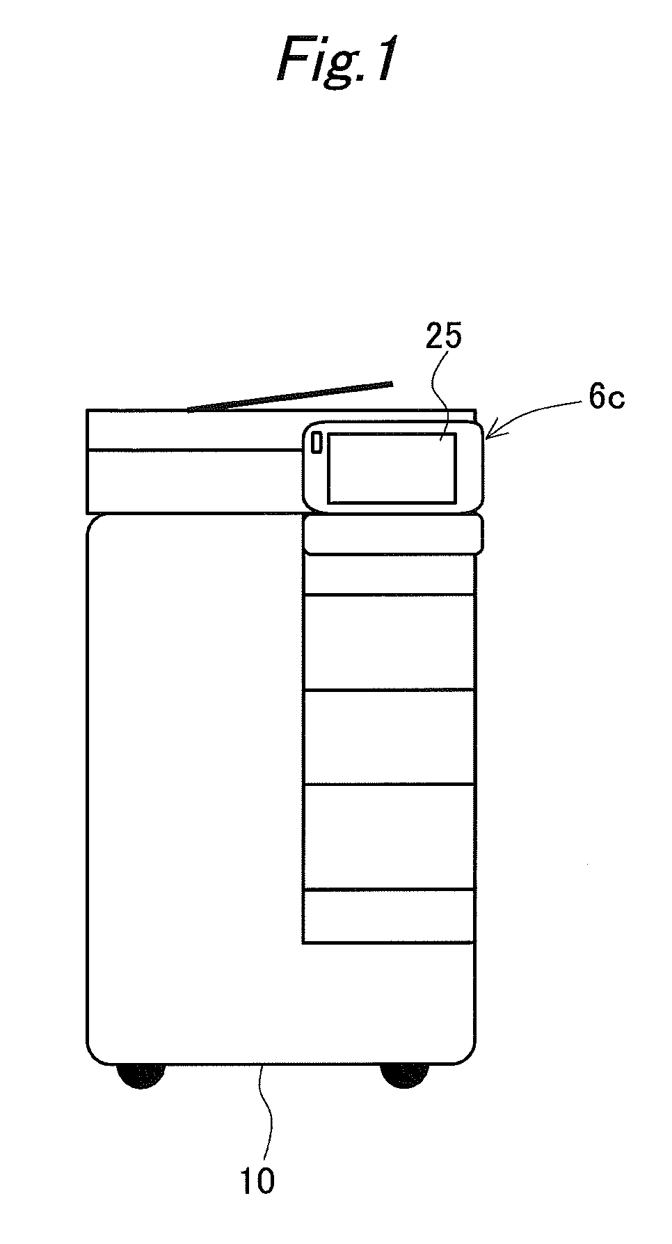
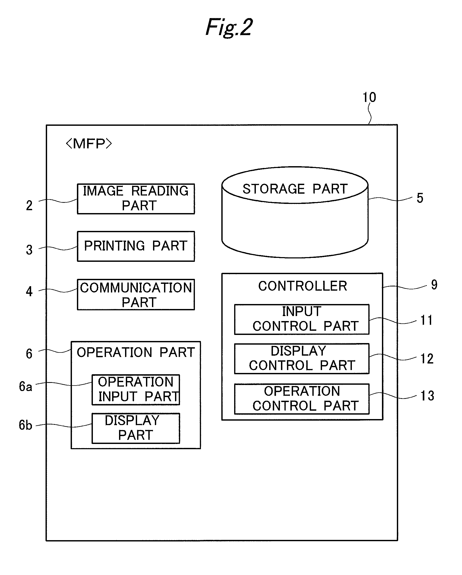
[0040]FIG. 1 is a view showing an appearance of an image transmission apparatus 10, and FIG. 2 is a view showing functional blocks of the image transmission apparatus 10. Herein, as an example of the image transmission apparatus 10, shown is an MFP (Multi-Functional Peripheral).

[0041]The MFP 10 is an apparatus (also referred to as a multifunction machine) having a scanner function, a copy function, a facsimile function, a box storage function, and the like. Specifically, as shown in the functional block diagram of FIG. 2, the MFP 10 comprises an image reading part 2, a printing part 3, a communication part 4, a storage part 5, an operation part 6, a controller (control part) 9, and the like and multiply uses these constituent parts to implement various functions.

[0042]The image reading part 2 is a processing part which optically reads an original manuscript p...


PUM


Abstract

An image transmission apparatus which transmits image data comprises an operation part displaying an operation screen and receiving a user operation on the operation screen and a processor for controlling a display content in the operation screen. The operation screen has a destination specifying area used for displaying a plurality of options which are candidates of destinations of the image data and receiving a specifying operation for specifying the destinations by using the plurality of options and a number display area used for displaying the number of the destinations specified by the specifying operation. The processor displays a destination list area used for listing the destinations specified by the specifying operation, together with the destination specifying area and the number display area, in the operation screen under the condition that a specific operation which is an operation on the number display area is received.

Description

[0001]The present invention claims priority under 35 U.S.C. §119 to Japanese Application No. 2014-111583 filed on May 29, 2014, the entire content of which is incorporated herein by reference.BACKGROUND OF THE INVENTION[0002]1. Field of the Invention[0003]The present invention relates to an image transmission apparatus such as an MFP (Multi-Functional Peripheral) or the like, and its relevant technique.[0004]2. Description of the Background Art[0005]In an image transmission by an MFP, a multi-address (multi-destination) transmission in which an image is transmitted simultaneously to a plurality of destinations (addresses) is sometimes performed. In more detail, a destination specifying area is displayed on a touch panel for operation in an MFP. In the destination specifying area, a plurality of options corresponding to a plurality of destinations, respectively, are arranged in alignment in one row or a plurality of rows. An operator finds a plurality of desired options among the plu...

Claims


Application Information

Patent Timeline
Patent Type & Authority Patents(United States)
IPC IPC(8): G06F3/12G06K15/00H04L29/08G06K15/02
CPCG06K15/002G06K15/1803H04L67/1095H04N1/00212H04N1/00
Inventor TOMIYASU, KAZUHIROMARUYAMA, TOMOKOKOMABA, KENICHINISHIMURA, RYOSUKE
Owner KONICA MINOLTA INC
Why Eureka
Try Eureka