Manual surgical ligation clip applier

a clip applier and manual technology, applied in the field of medical devices, can solve the problems of limited space and visibility, time-consuming and difficult to perform complex manipulations, and the use of surgical threads for ligation, so as to maintain the clamping pressure on the vessel and effective clip delivery

Active Publication Date: 2016-10-04
TELEFLEX MEDICAL INC
View PDF71 Cites 80 Cited by
  • Summary
  • Abstract
  • Description
  • Claims
  • Application Information

AI Technical Summary

Benefits of technology

[0016]The polymeric clips will be positioned in clip cartridges. The clips will then be loaded into the applier manually by pressing the distal end of the applier down on the end of the clip. The will be guided by features on the cartridge and will grab the clip in the clip catch mechanism internal to the applier. When the applier is pulled away from the cartridge the clip will release from the cartridge and stay internal to the applier. A clip indicator internal to the applier will indicate that a clip is present at the proximal end of the applier shaft. This will allow the user to know a clip is present prior to and during insertion / manipulation of the applier.
[0017]The jaws will be able to actuate without disturbing the loaded clip. This allows the jaws to be used in the dissection and grasping of tissue around the vessel being ligated if necessary.

Problems solved by technology

The use of surgical thread for ligation requires complex manipulations of the needle and suture material to form the knots required to secure the vessel.
Such complex manipulations are time-consuming and difficult to perform, particularly in endoscopic surgical procedures, which are characterized by limited space and visibility.
But, with the advent of high technology diagnostic techniques using computer tomography (CATSCAN) and magnetic resonance imaging (MRI), metallic clips have been found to interfere with the imaging techniques.
However this clip is: (i) rudimentary in construction, (ii) does not provide adequate clip closing or clamping strength, (iii) lacks any complex geometry which would adequately retain the clip in a closed position, and further (iv) is too unstable when closed to be safely applied over vessels.
Prior art polymeric and metal clips do not lend themselves to deployment through small diameter instrumentation, such as, for example, a ˜5 mm endoscope.
Such closure of a clip having locking parts at its distal end generally causes or requires dissection, removal, or clearance of additional surrounding tissue, in order to allow the clip's locking features to come together, and / or due to actuation of an applier tool surrounding or applied against the distal clip ends, requiring additional time during a surgical procedure and damage to tissue.
In these cases, the locking feature may have difficulty penetrating the tissue or may have difficulty locking after it has penetrated the tissue.
This technique may also result in unintended penetration of tissue or vessels.

Method used


Image

  • Manual surgical ligation clip applier
  • Manual surgical ligation clip applier
  • Manual surgical ligation clip applier

Examples


first embodiment

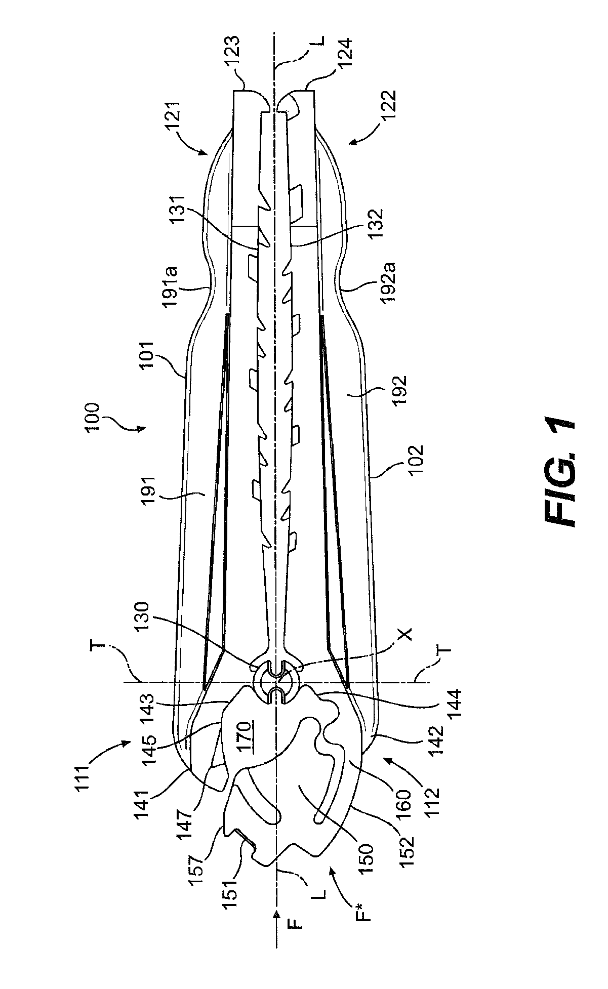
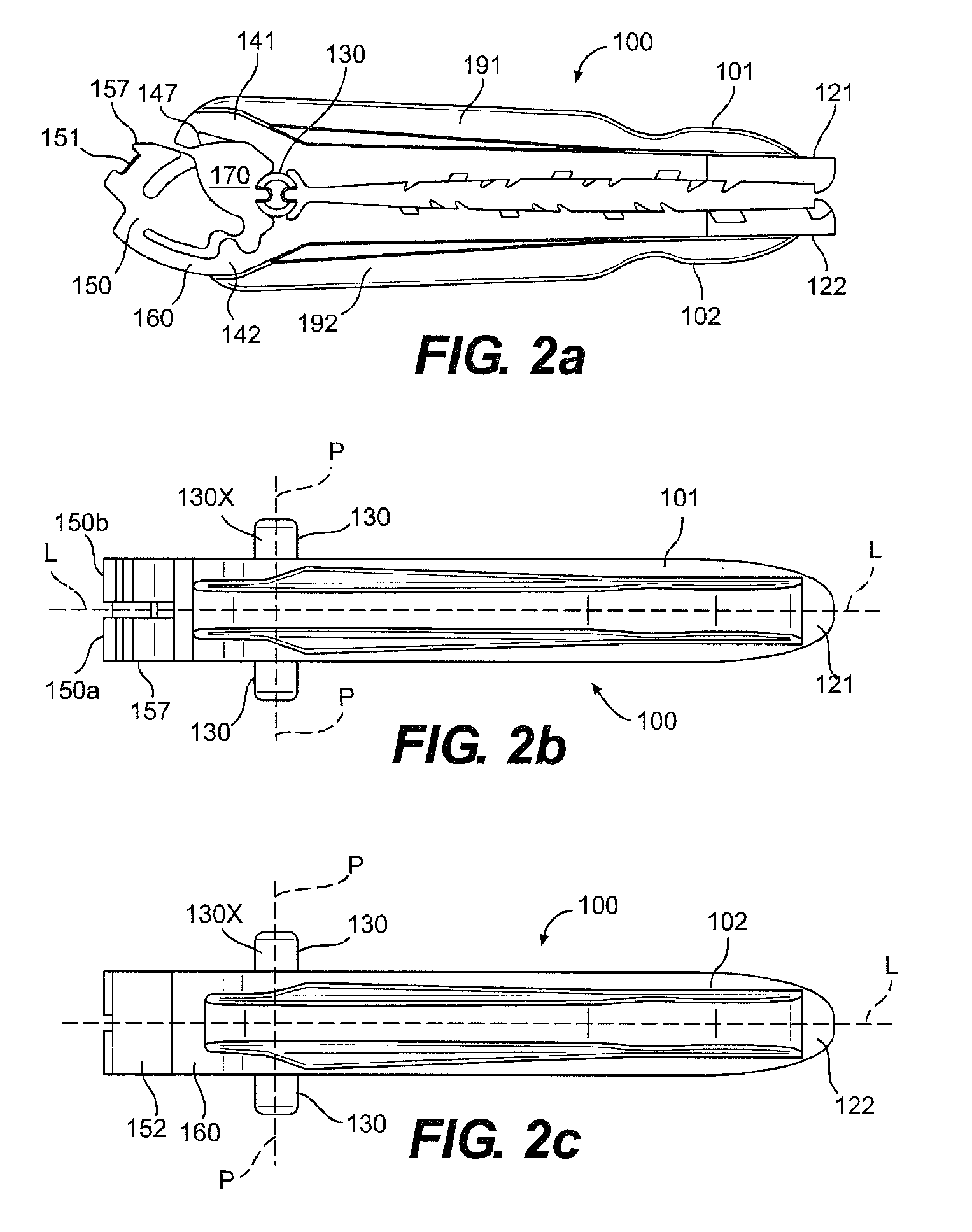
[0148]FIG. 1 shows a view of a surgical ligation clip 100 in accordance with present invention. The clip 100 defines a longitudinal axis “L” along its longest dimension and includes a first leg 101 and a second leg 102 each extending along the longitudinal axis L and having proximal 111, 112 and distal 121, 122 end portions with respect to said longitudinal axis. As used herein, the term “proximal” shall refer to the portion of the clip referenced herein which is away from the tips of the clip which open, and “distal” shall refer to the portion of the clip at the tips which open, in accordance with the convention that the clip is inserted distal tip first through an instrument towards an anatomical body to be ligated, such that distal generally refers to the direction away from the user or applier of the surgical clip and proximal refers to the direction opposite to distal.

[0149]In clip 100, a clip hinge 130 joins the first and second legs 101, 102 at a point on their respective pro...

second embodiment

[0196]In the handle, the trigger functions are reversed so that the upper trigger actuates the jaws and the lower trigger actuates the clip delivery mechanisms.

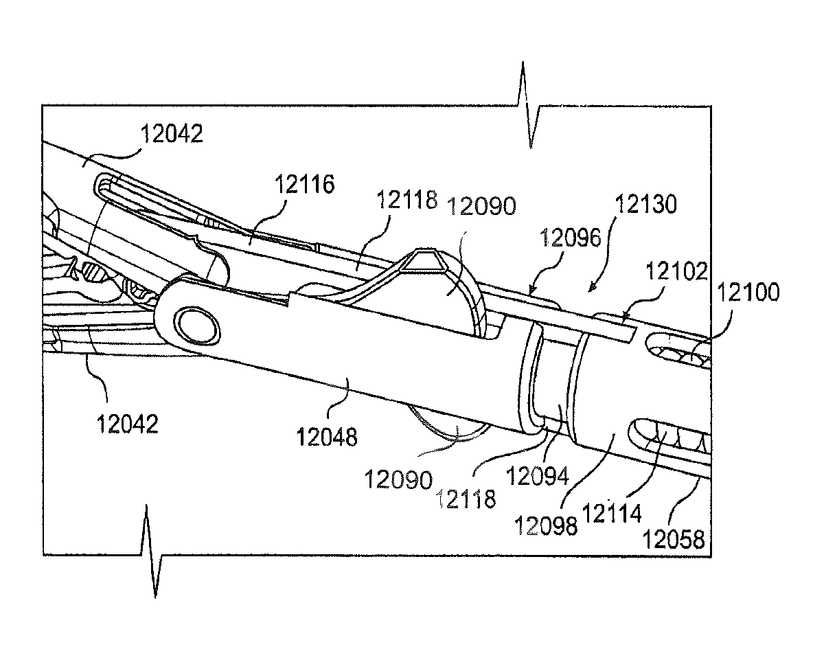
[0197]The distal portion of the applier is connected to the handle through the multi stage transmission, see FIGS. 65-68. One embodiment of the transmission is made up of a two piece outer shell which acts as the bearing to allow the rotation of the distal end. Internal to the shell are features that guide the internal components during the actuation sequences of the applier. There are two jaw links that connect to the inner tube of the distal end and provide the grove for the inner features of the lower trigger linkages. The jaw links snap together and ride on the internal surface of the transmission shell. The area between the jaw links is open to allow for additional transmission parts. There are two center spindles that snap together and attach to the wedges, the interior surface of the center spindles provide a guide for...


PUM


Abstract

A ligation clip applier is provided. The clip applier includes: a pair of jaws; a distal clevis tube to which the jaws are pivotally mounted; a proximal clevis tube located behind the distal clevis tube, wherein the distal clevis tube and the proximal clevis tubes move axially with respect to each other; a clip lock actuator fixed to one of the proximal and distal clevis tubes; and a distal pushrod extending through the distal and proximal clevis tubes and forming a camming connection with the jaws configured to close and move the jaws toward a proximal direction toward the clip lock actuator when the distal pushrod is moved in the proximal direction. A method for applying a clip on a vessel is disclosed.

Description

CROSS-REFERENCE TO RELATED APPLICATIONS[0001]This application claims priority to provisional U.S. patent application entitled, Manual Surgical Ligation Clip Applier, filed Sep. 15, 2011, having a Ser. No. 61 / 535,190, the disclosure of which is hereby incorporated by reference in its entirety.FIELD OF THE INVENTION[0002]The present invention relates to medical devices and, in particular, a device for applying surgical clips for ligation of vessels or tissue.BACKGROUND[0003]Many surgical procedures require vessels or other fluid ducts or tissue conduits and structures to be ligated during the surgical process, such as, for example, veins or arteries in the human body. For example, many surgical procedures require cutting blood vessels, and these blood vessels may require ligation to reduce bleeding. In some instances, a surgeon may wish to ligate the vessel temporarily to reduce blood flow to the surgical site during the surgical procedure. In other instances a surgeon may wish to per...

Claims


Application Information

Patent Timeline
Patent Type & Authority Patents(United States)
IPC IPC(8): A61B17/10A61B17/128A61B17/122
CPCA61B17/128A61B17/122A61B17/1285A61B17/12A61B90/03A61B17/1222A61B2017/12004
Inventor WILLETT, LYNNSCHMIDT, PHILIPMONAHAN, DANLEHMAN, ADAMADAMS, LELAND RAYWHITING, PAULCASTRO, SALVATOREBACHMAN, ALAN
Owner TELEFLEX MEDICAL INC
Why Eureka
Try Eureka