Accelerator pedal apparatus

a pedal apparatus and accelerator technology, applied in the direction of mechanical control devices, process and machine control, instruments, etc., can solve the problems of inability to completely return the pedal arm to the rest position, and inability to perform stable active control operation. , to achieve the effect of shortening the arm length of rotation torque, and reducing the number of parts

Active Publication Date: 2016-10-04
MIKUNI CORP
View PDF26 Cites 3 Cited by
  • Summary
  • Abstract
  • Description
  • Claims
  • Application Information

AI Technical Summary

Benefits of technology

[0010]Therefore, it is one aspect to provide an accelerator pedal apparatus capable of performing active control with quick response while achieving structural simplification, parts count reduction, cost reduction, entire apparatus miniaturization, and the like.
[0015]In particular, the first distance from the contact position of the pedal arm with the contact portion of the rotation member to the first rotation axis line of the pedal arm may be formed longer than the second distance from the contact position of the pedal arm with the contact portion of the rotation member to the second rotation axis line of the rotation member. In addition, the pedal arm may include the contact section formed so that the contact portion is displaced to be farther from the first rotation axis line while being contacted to the contact section when the pedal arm is rotated toward the maximum depression position and so that the contact portions is displaced to be closer to the first rotation axis line while being contacted to the contact section when the pedal arm is rotated toward the rest position. Accordingly, the operational angle may be widened as shortening arm length of rotation torque exerted to the pedal arm by the rotation member. Therefore, stable drive force, that is, reaction force (i.e., resistance force) can be generated while achieving miniaturization of the drive source and the entire apparatus.
[0016]According to an aspect, it is possible to obtain an accelerator pedal apparatus capable of performing active control with quick response while achieving structural simplification, parts count reduction, cost reduction, entire apparatus miniaturization, and the like.

Problems solved by technology

Therefore, variation in the electromagnetic drive force is directly transmitted to the pedal arm to cause a fear that stable active control operation cannot be performed.
Therefore, when the movable operation member is fixed to be non-movable in a state that the spring is compressed, there is a fear that the pedal arm cannot be returned completely to the rest position.
Therefore, variation in the drive force (i.e., the torque) within the operational range of the torque motor is directly transmitted to the pedal arm via the plunger element to cause a fear that stable active control operation cannot be performed.
Therefore, when the plunger element is fixed to be non-movable in a state that the spring is compressed, there is a fear that the pedal arm cannot be returned completely to the rest position.

Method used


Image

  • Accelerator pedal apparatus
  • Accelerator pedal apparatus
  • Accelerator pedal apparatus

Examples


Embodiment Construction

[0024]Reference will now be made in detail to embodiments, examples of which are illustrated in the accompanying drawings, wherein like reference numerals refer to like elements throughout.

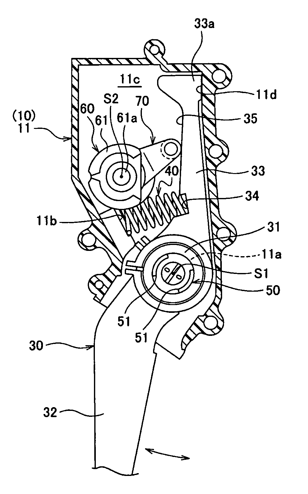
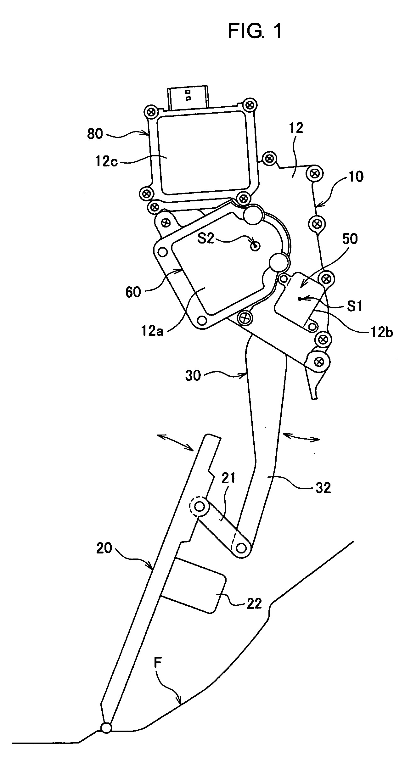
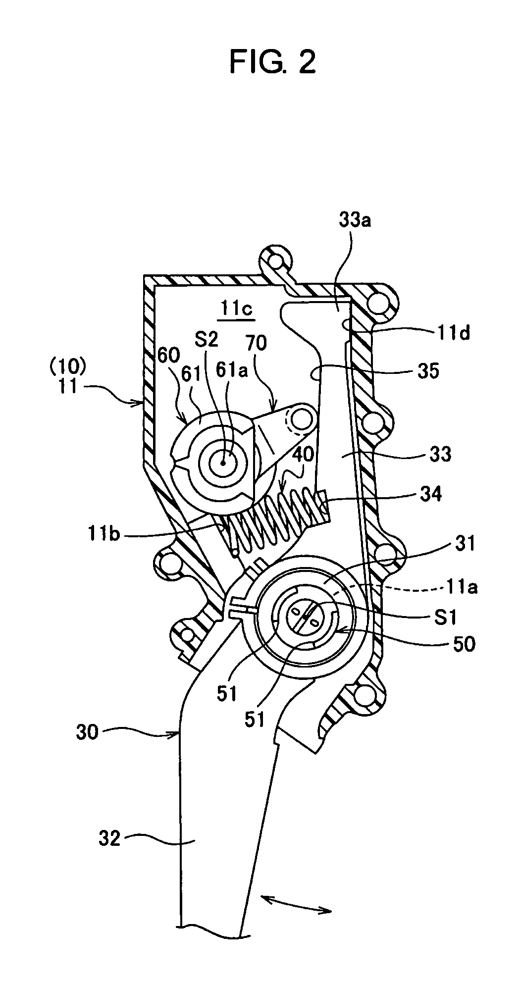
[0025]As illustrated in FIGS. 1 to 3, the accelerator pedal apparatus includes a housing 10 fixed to a vehicle body of an automobile and the like, an accelerator pedal 20 supported swingably to a floor face F of the vehicle body, a pedal arm 30 supported rotatably having a predetermined first rotation axis line S1 defined by the housing 10 as the center between a rest position to a maximum depression position (i.e., a rotation range) while being interlocked with the accelerator pedal 20, a return spring 40 to exert urging force to return the pedal arm 30 toward the rest position, a position sensor 50 to detect a rotational angle position of the pedal arm 30, a drive source 60 and a rotation member 70 being rotatable around a second rotation axis line S2 defined by a drive shaft 61a of the drive so...


PUM


Abstract

An accelerator pedal apparatus includes a pedal arm rotating around a first rotation axis line, a return spring and a reaction force adding mechanism including a drive source and a rotation member rotating around a second rotation axis line and having a contact portion contacted to the pedal arm which adds reaction force in the direction to return the pedal arm to the rest position. A first distance from the contact position of the pedal arm with the contact portion to the first rotation axis line is longer than a second distance to the second rotation axis line. The pedal arm includes a contact section having the contact portion displaced while being contacted so that the contact portion is to be farther from the first rotation axis line when rotating toward the maximum depression position and to be closer to the first rotation axis line when rotating toward the rest position.

Description

CROSS-REFERENCE TO RELATED APPLICATIONS[0001]This application claims the priority benefit of Japanese Patent Application No. 2009-218639, filed on Sep. 24, 2009 in the Japanese Patent Office, the disclosure of which is incorporated herein by reference.BACKGROUND[0002]1. Field[0003]Embodiments relate to an accelerator pedal apparatus applied to vehicles and the like having a drive-by-wire system, and in particular, relates to an accelerator pedal apparatus capable of performing active control to generate reaction force (i.e., resistance force or press-back force) against tread force of a pedal arm for danger avoidance, danger notification, fuel consumption improvement, and the like.[0004]2. Description of the Related Art[0005]An accelerator pedal apparatus adopted to an electronically controlled throttle system (i.e., a drive-by-wire system) for an engine mounted on an automobile and the like includes a pedal arm (i.e., a pedal element) being rotatably supported to a housing (i.e., a...

Claims


Application Information

Patent Timeline
Patent Type & Authority Patents(United States)
IPC IPC(8): B60K26/02G05G1/44G05G5/03
CPCB60K26/021G05G5/03G05G1/44Y10T74/20534
Inventor OSAWA, TSUYOSHIKUMAMOTO, MASATOFUKUSHIMA, YOSHITOMOKIKUCHI, KOUJISHIMIZU, TSUYOSHIKAWADE, HISASHITOUHACHI, HIROMUTSU
Owner MIKUNI CORP
Why Eureka
Try Eureka