Optical and temperature feedbacks to control display brightness

a technology of temperature feedback and display brightness, which is applied in the field of backlight system, can solve the problems of changing the characteristics of light sources with age, and achieve the effect of increasing the current level of lamps and facilitating displays

Active Publication Date: 2007-02-27
POLARIS POWERLED TECH LLC
View PDF32 Cites 121 Cited by
  • Summary
  • Abstract
  • Description
  • Claims
  • Application Information

AI Technical Summary

Benefits of technology

[0006]One embodiment of the present invention is an illumination control circuit which allows a user to set a desired brightness level and maintains the desired brightness level over temperature and life of a light source (e.g., a fluorescent lamp). The illumination control circuit uses an optical sensor (e.g., a visible light sensor) to maintain consistent brightness over lamp life and over extreme temperature conditions. The illumination control circuit further includes a temperature sensor to monitor lamp temperature and prolongs lamp life by reducing power to the fluorescent lamp when the lamp temperature is excessive. In one embodiment, the illumination control circuit optionally monitors ambient light and automatically adjusts lamp power in response to variations for optimal power efficiency.
[0009]In one embodiment, an illumination control circuit includes an optical or a thermal feedback sensor integrated with control circuitry to provide adjustment capabilities to compensate for temperature variations, to disguise aging, and to improve the response speed of the light source. For example, LCD computer monitors make extensive use of sleep functions for power management. The LCD computer monitors exhibit particular thermal characteristics depending on the sleep mode patterns. The thermal characteristics affect the “turn on” brightness levels of the display. In one embodiment, the illumination control circuit operates in a boost mode to expedite the display to return to a nominal brightness after sleep mode or an extended off period.
[0010]In one embodiment, a light sensor (e.g., an LX1970 light sensor from Microsemi Corporation) is coupled to a monitor to sense the perceived brightness of a CCFL used in the backlight or display. For example, the light sensor can be placed in a hole in the back of the display. The light sensor advantageously has immunity to infrared light and can accurately measure perceived brightness when the CCFL is in a warming mode. The output frequency of the CCFL shifts from infrared to the visible light spectrum as the temperature increases during the warming mode.
[0013]Providing a boost current to the CCFL during initial activation or reactivation from sleep mode of the display improves the response time of the display. For example, the display brightness may be in the range of 40%–50% of the nominal range immediately after turn on. Using a normal start up current (e.g., 8 mA) at 23 degrees C., the 90% brightness level may be achieved in 26 minutes. Using a 50% boost current (e.g., 12 mA), the 90% brightness level may be achieved in 19 seconds. The boost level can be adjusted as desired to vary the warm-up time of the display. The warm-up time is a function of the display or monitor settling temperature. For example, shorter sleep mode periods mean less warm-up times to reach the 90% brightness level.
[0014]In one embodiment, the boost control function can be implemented with low cost and low component count external circuitry. The boost control function enhances the performance of the display monitor for a computer user. For example, the display monitor is improved by reducing the time to reach 90% brightness by 50 to 100 times. The boost control function benefits office or home computing environments where sleep mode status is frequent. Furthermore, as the size of LCD display panels increase in large screen displays, the lamp length and chassis also increase. The larger lamp and chassis leads to system thermal inertia, which slows the warm-up time. The boost control function can be used to speed up the warm-up time.
[0016]In one embodiment, the boost control circuit is part of the optical feedback loop and facilitates a display that is capable of compensating for light output degradation over time. For example, as the lamp output degrades over usage hours, the lamp current level can be increased to provide a consistent light output. LCD televisions and automotive GPS / Telematic displays can offer substantially the same brightness provided on the day of purchase after two years of use.

Problems solved by technology

Furthermore, the characteristics of the light source change with age.

Method used


Image

  • Optical and temperature feedbacks to control display brightness
  • Optical and temperature feedbacks to control display brightness
  • Optical and temperature feedbacks to control display brightness

Examples


Embodiment Construction

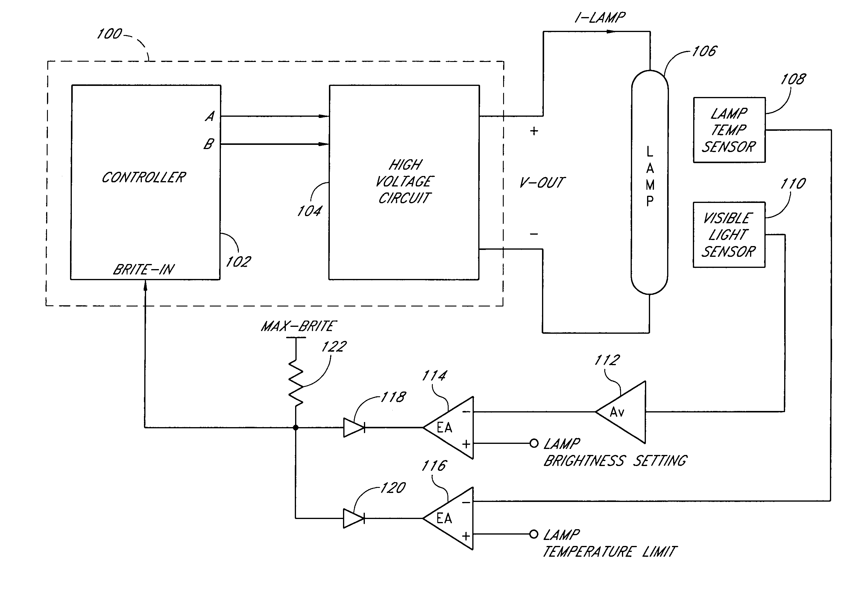
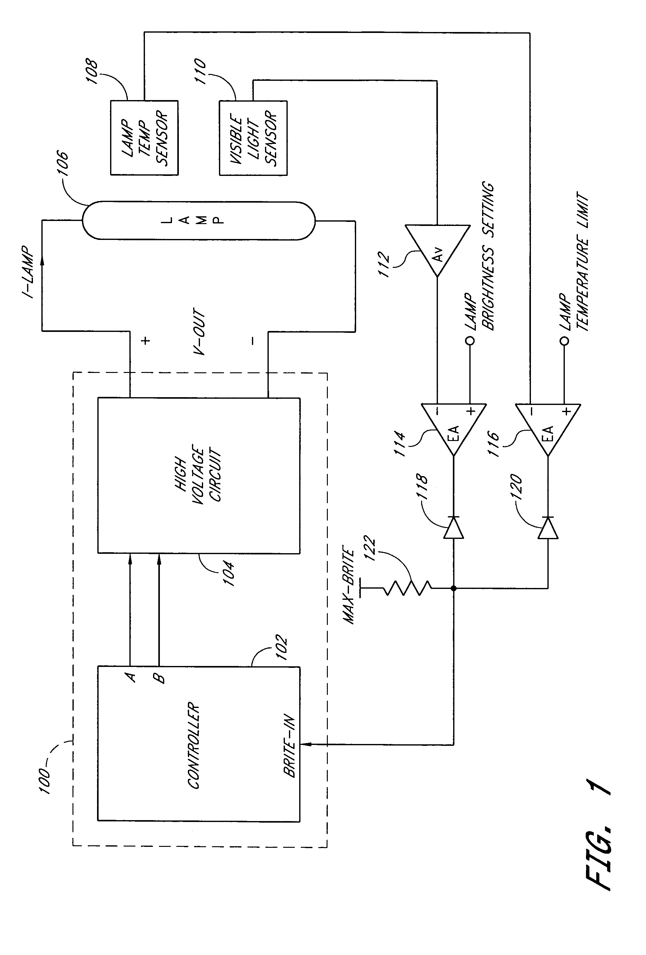
[0031]Various embodiments of the present invention will be described hereinafter with reference to the drawings. FIG. 1 is a block diagram of a power conversion circuit (or backlight system) with dual feedback loops in accordance with one embodiment of the invention. The backlight system may be advantageously used in automotive applications which are exposed to relatively extreme temperature variations and suffer brightness loss at low ambient temperatures. The backlight system can also be used in other LCD applications, such as computer notebooks, computer monitors, handheld devices, television displays, and the like. The dual feedback loops allow a user to set a desired brightness level for a backlight light source and maintain the desired brightness level over operating temperature and over degradation of the light source efficacy over life. The dual feedback loops also extend the useful life of the light source by maintaining safe operating conditions for the light source.

[0032]...


PUM


Abstract

An illumination control circuit allows a user to set a desired brightness level and maintains the desired brightness level over temperature and life of a light source. The illumination control circuit uses a dual feedback loop with both optical and thermal feedbacks. The optical feedback loop controls power to the light source during normal operations. The thermal feedback loop overrides the optical feedback loop when the temperature of the light source becomes excessive.

Description

CLAIM FOR PRIORITY[0001]This application claims the benefit of priority under 35 U.S.C. § 119(e) of U.S. Provisional Application No. 60 / 505,074 entitled “Thermal and Optical Feedback Circuit Techniques for Illumination Control,” filed on Sep. 23, 2003, the entirety of which is incorporated herein by reference.BACKGROUND OF THE INVENTION [0002]1. Field of the Invention[0003]The present invention relates to a backlight system, and more particularly relates to using optical and temperature feedbacks to control the brightness of the backlight.[0004]2. Description of the Related Art[0005]Backlight is used in liquid crystal display (LCD) applications to illuminate a screen to make a visible display. The applications include integrated displays and projection type systems, such as a LCD television, a desktop monitor, etc. The backlight can be provided by a light source, such as, for example, a cold cathode fluorescent lamp (CCFL), a hot cathode fluorescent lamp (HCFL), a Zenon lamp, a meta...

Claims


Application Information

Patent Timeline
Patent Type & Authority Patents(United States)
IPC IPC(8): H05B37/02G09G3/36H05B41/285H05B41/38H05B41/392
CPCH05B41/3922H05B41/2858H05B41/386H05B41/2856G09G3/3406G09G2320/041G09G2320/062
Inventor FERGUSON, BRUCE R.HENRY, GEORGE C.HOLLIDAY, ROGER
Owner POLARIS POWERLED TECH LLC
Why Eureka
Try Eureka