Pixel structure with multiple transfer gates

a pixel structure and transfer gate technology, applied in the field of pixel structures and arrays of pixel structures, can solve the problems of limited ratio between the brightest and darkest image values that can be resolved by the image sensor, colour reconstruction is difficult, and exposure period is different for different parts of the response curve, so as to achieve high dynamic range, increase dynamic range, and complex pixel implementation

Active Publication Date: 2012-01-05
CMOSIS
View PDF10 Cites 118 Cited by
  • Summary
  • Abstract
  • Description
  • Claims
  • Application Information

AI Technical Summary

Benefits of technology

[0004]Other techniques have been proposed for increased dynamic range, like pixels with time-to-saturation counters, but they result in much more complex pixel implementations. One technique to achieve a high dynamic range uses different gain in the readout path (e.g. B. Fowler, “Wide Dynamic Range Low Light Level CMOS Image Sensor”, proc. International Image Sensor Workshop, Bergen, June 2009). The photodiode signal is read out through a single floating diffusion, which must be designed to handle the maximum charge packet that is read out from the pixel. This method only solves the dynamic range limitations in the readout chain outside of the pixel array.

Problems solved by technology

When used in image sensors, such as CMOS active pixel image sensors, this limits the ratio between the brightest and darkest image values that can be resolved by the image sensor.
In such pixels, colour reconstruction is difficult since it is not exactly known which slope is used close to the kneepoints of the image.
Another disadvantage of such pixels is that the exposure period is different for different parts of the response curve.
This results in distortion artefacts in moving images.
Other techniques have been proposed for increased dynamic range, like pixels with time-to-saturation counters, but they result in much more complex pixel implementations.
This method only solves the dynamic range limitations in the readout chain outside of the pixel array.
This requires subsequent readings from the pixel, which results in more time required to read the pixel data.
Furthermore, the voltage control of the transfer gate is important, and threshold voltage variations on transfer gates will cause pixel-to-pixel non-uniformities in the different transfers.

Method used


Image

  • Pixel structure with multiple transfer gates
  • Pixel structure with multiple transfer gates
  • Pixel structure with multiple transfer gates

Examples


Embodiment Construction

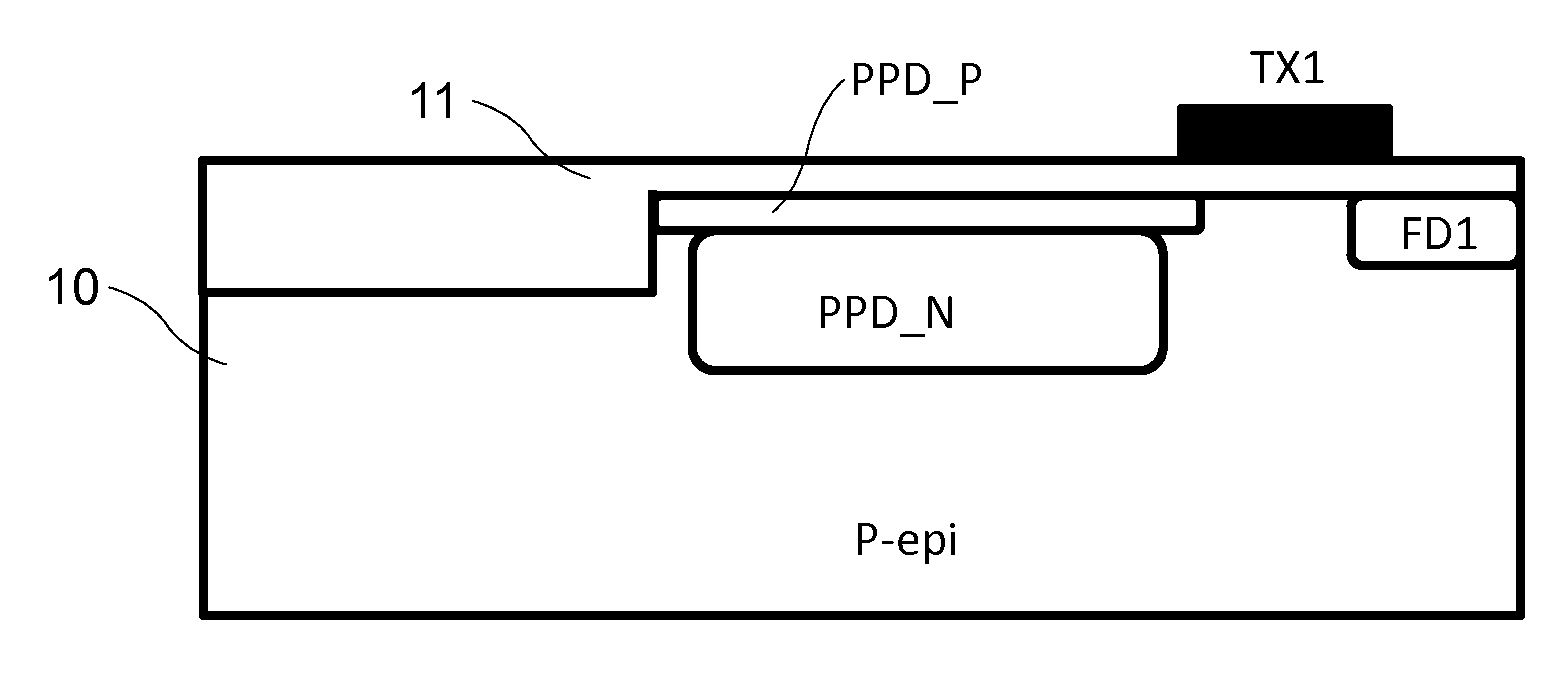
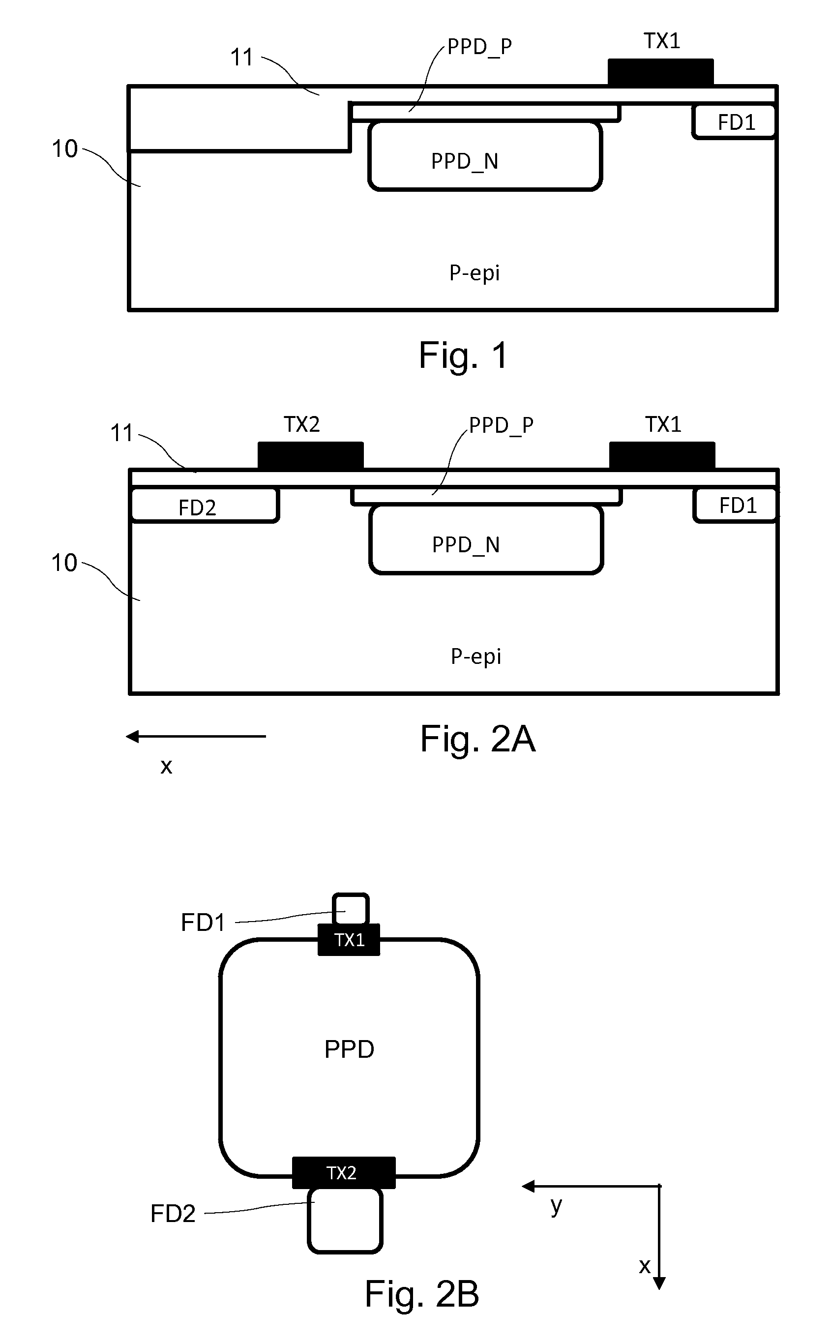
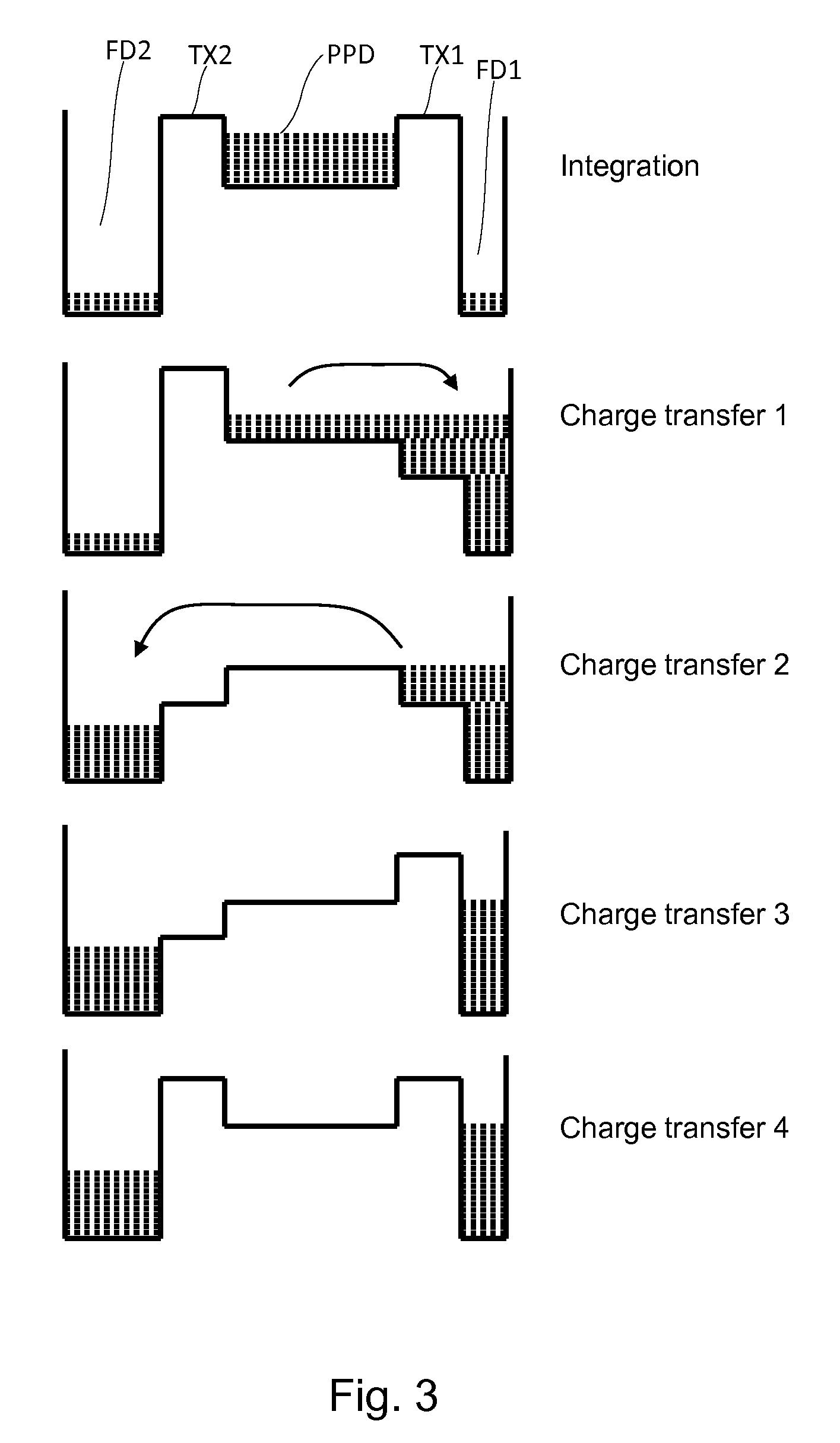
[0048]The present invention will be described with respect to particular embodiments and with reference to certain drawings but the invention is not limited thereto but only by the claims. The drawings described are only schematic and are non-limiting. In the drawings, the size of some of the elements may be exaggerated and not drawn on scale for illustrative purposes. Where the term “comprising” is used in the present description and claims, it does not exclude other elements or steps. Furthermore, the terms first, second, third and the like in the description and in the claims, are used for distinguishing between similar elements and not necessarily for describing a sequential or chronological order. It is to be understood that the terms so used are interchangeable under appropriate circumstances and that the embodiments of the invention described herein are capable of operation in other sequences than described or illustrated herein.

[0049]The terms “horizontal” and “vertical” are...


PUM


Abstract

A pixel structure comprises a photo-sensitive element for generating charge in response to incident light. A first transfer gate is connected between the photo-sensitive element and a first charge conversion element. A second transfer gate is connected between the photo-sensitive element and a second charge conversion element. An output stage outputs a first value related to charge at the first charge conversion element and outputs a second value related to charge at the second charge conversion element. A controller controls operation of the pixel structures and causes a pixel structure. The controller causes the pixel structure to: acquire charges on the photo-sensitive element during an exposure period; transfer a first portion of the charges acquired during the exposure period from the photo-sensitive element to the first charge conversion element via the first transfer gate; and transfer a second portion of the charges acquired during the exposure period from the photo-sensitive element to the second charge conversion element via the second transfer gate.

Description

FIELD OF THE INVENTION[0001]This invention relates to pixel structures and to arrays of pixel structures which can be used in applications such as image sensors.BACKGROUND TO THE INVENTION[0002]Pixel structures, as used in image sensors and other sensor applications, have a finite dynamic range. The dynamic range is the range, typically expressed as a ratio, between the largest intensity value that can be resolved by the pixel and the smallest intensity value that can be resolved by the pixel. When used in image sensors, such as CMOS active pixel image sensors, this limits the ratio between the brightest and darkest image values that can be resolved by the image sensor. The smallest intensity value is limited by the read noise of the pixel. The largest intensity value is limited by the amount of charges that can be stored inside the pixel and effectively read out.[0003]Various techniques have been proposed to extend the dynamic range. A summary of various high dynamic range techniqu...

Claims


Application Information

Patent Timeline
Patent Type & Authority Applications(United States)
IPC IPC(8): H04N5/335
CPCH01L27/14603H01L27/14609H01L27/14656H01L27/14641H04N5/3742H04N5/3745H04N5/35572H04N25/587H04N25/767H04N25/77H04N25/59H04N25/00
Inventor WANG, XINYANGMEYNANTS, GUYWOLFS, BRAM
Owner CMOSIS
Why Eureka
Try Eureka