Wide area neutralizer
a neutralizer and wide-area technology, applied in the field of weapons systems, can solve the problems of time-consuming and inefficient closing process required in order to eliminate the threat of missile launching, and the requirement of constant surveillance followed by a swift and accurate strike is often unmet by many armed forces
- Summary
- Abstract
- Description
- Claims
- Application Information
AI Technical Summary
Benefits of technology
Problems solved by technology
Method used
Image
Examples
second embodiment
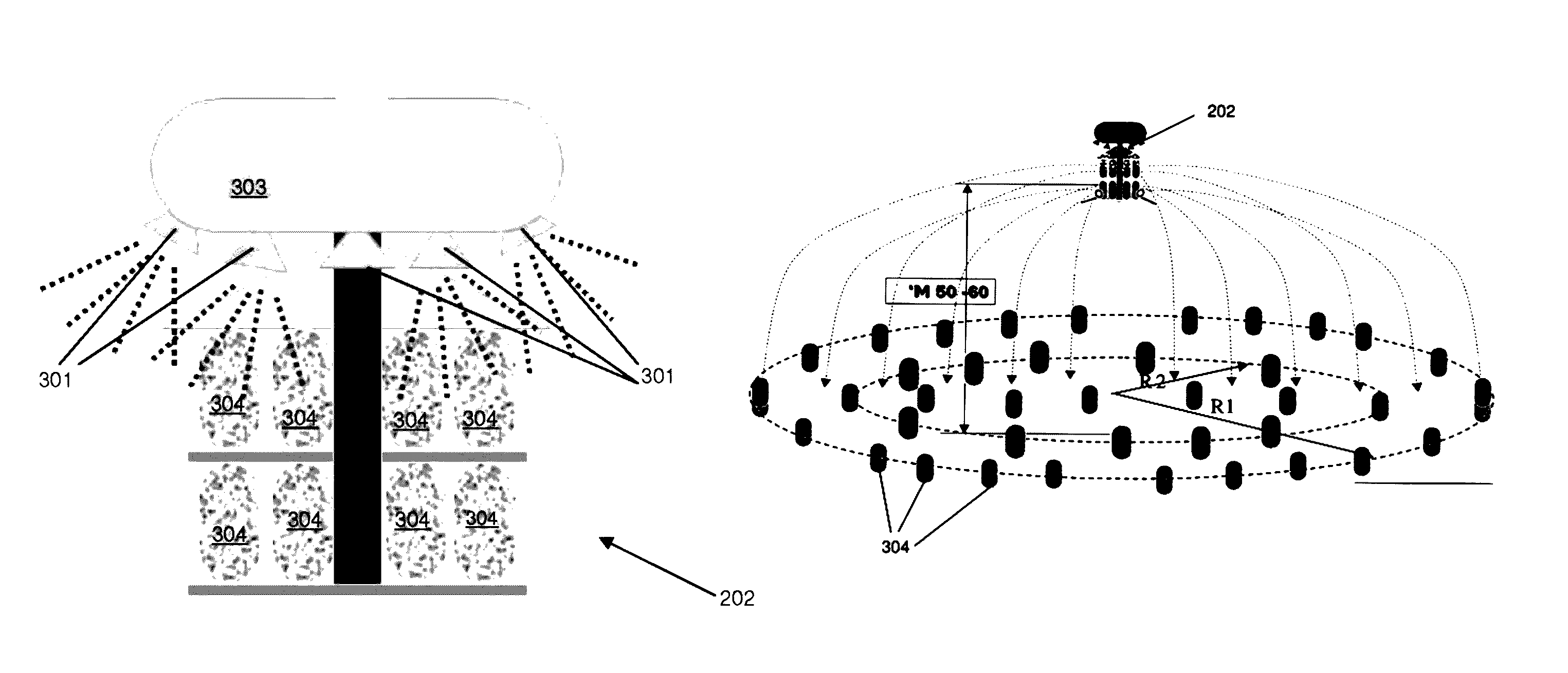
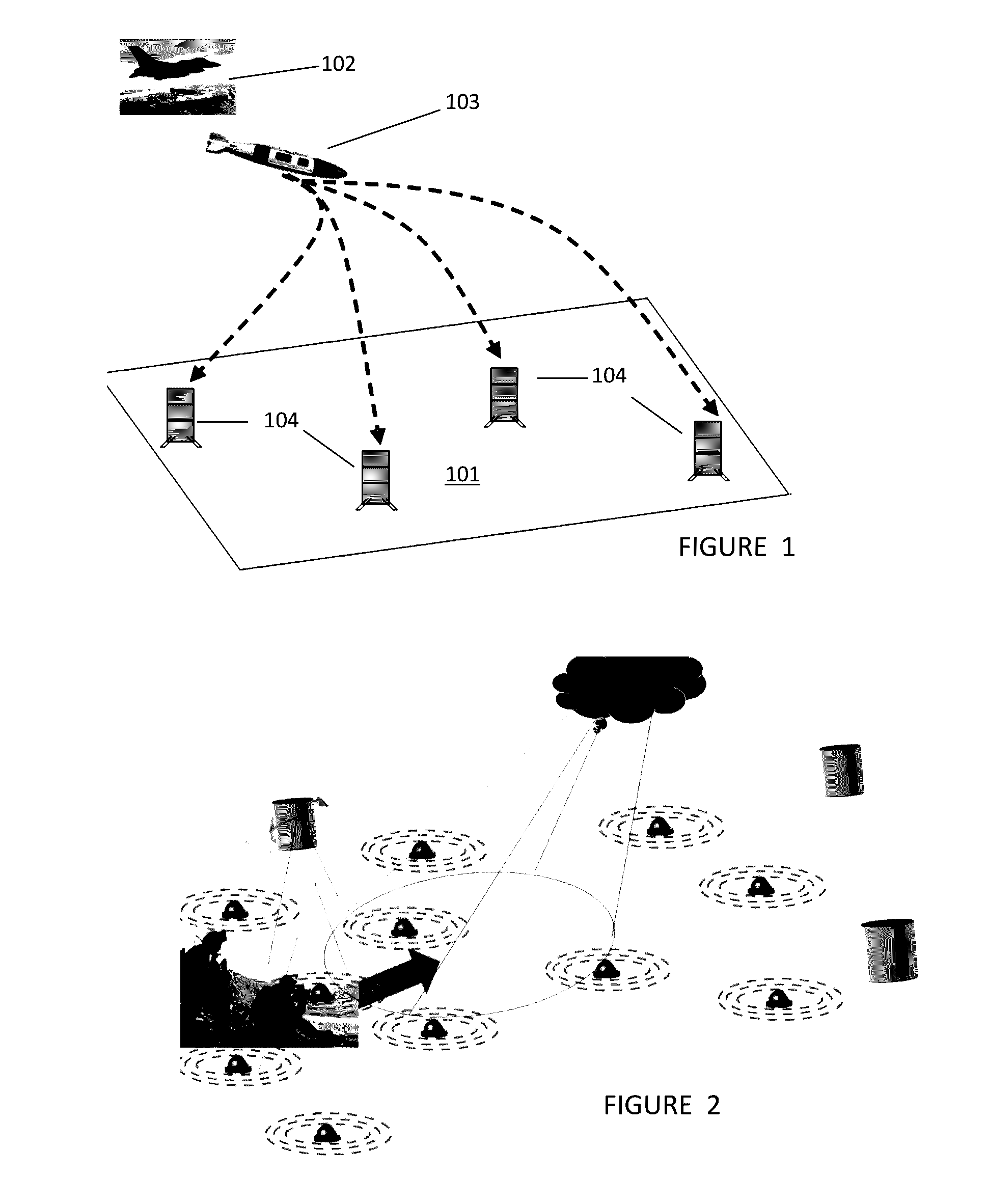
[0090]In warhead 202, as illustrated in FIG. 11, two or more circular warheads 202 are stacked one over another within a barrel shaped WAN component 104. Each warhead 202 includes an angular wedge-shaped munitions body 304. Upon activation, the is previously dormant WAN component 104 levels using an electric motor aiming system. An electric motor rotating system rotates the stack so that wedge 304 of the topmost warhead 202 faces enemy forces 106. Controller 204 programs vertical lift rockets 301 of the topmost warhead 202 to launch topmost warhead 202 to the height above the ground at which the detonation of wedge 304 of the topmost warhead 202 creates the required distruction area 110. At the required height above the ground wedge-shaped munitions body 304 explodes releasing numerous metal fragments, thereby creating an angular shaped destruction area 110. Following the vertical launch of the topmost warhead 202 from WAN component 104, a new warhead 202 that was previously stacked...
third embodiment
[0091]In warhead 202, a circular “bowl shape” warhead 305 is used. Warhead 305 is placed within a WAN component 306, as shown in FIG. 13, and upon activation is rotated to the desired launch heading. The warhead launching angle is then fixed by a second motor system, and “bowl shape” warhead 305 is launched at a known heading, angle and velocity. When launched, warhead 305 may also spin about its central axis of circular symmetry for stabilizing purposes. This “bowl shaped” warhead 305 is launched in a “frisbee” type flight pattern, in which gyroscopic forces created by horizontal spinning of the warhead 305 account for the warhead 305 balanced flight. In order to create the horizontal rotation of the warhead 305 during launch, a rope may be attached to the circumference of the “bowl shaped” warhead. During warhead 305 launch, the attached rope creates a force which spins the warhead 305 around its horizontal axis in addition to the linear warhead launch force, as seen in FIG. 13A. ...
fourth embodiment
[0096]In a third and fourth embodiment a “football” shaped munitions body is packed into any to warhead. This munitions body may be a complete football shape, as illustrated in FIG. 17, or a “candy wrapping” shape in which the original “football” shape has two additional faces on either end, enhancing the metal fragment density at the extreme edges of the destruction area. The “candy wrapping” munitions body is illustrated in FIG. 18. The “football” shaped munitions body illustrated in FIG. 17, may contain metal fragments at the entire circumference of the munitions body and may therefore open up prior to detonation of munitions body and fragment dispersion. This option is described in FIG. 18A.
PUM
 Abstract
Description
Claims
Application Information
 - R&D
- Intellectual Property
- Life Sciences
- Materials
- Tech Scout
- Unparalleled Data Quality
- Higher Quality Content
- 60% Fewer Hallucinations
Browse by: Latest US Patents, China's latest patents, Technical Efficacy Thesaurus, Application Domain, Technology Topic, Popular Technical Reports.
© 2025 PatSnap. All rights reserved.Legal|Privacy policy|Modern Slavery Act Transparency Statement|Sitemap|About US| Contact US: help@patsnap.com


