

Optical imaging system
an optical imaging system and optical element technology, applied in the field of optical imaging systems, can solve the problems of inability to meet the requirements of thin smartphones and small-size tablets, the size of the optical elements and the volume of the imaging system is increasingly large, and achieves the effect of preventing the overlap of optical components and thin thickness of the optical system
- Summary
- Abstract
- Description
- Claims
- Application Information
AI Technical Summary
Benefits of technology
Problems solved by technology
Method used
Image

Examples
example 1
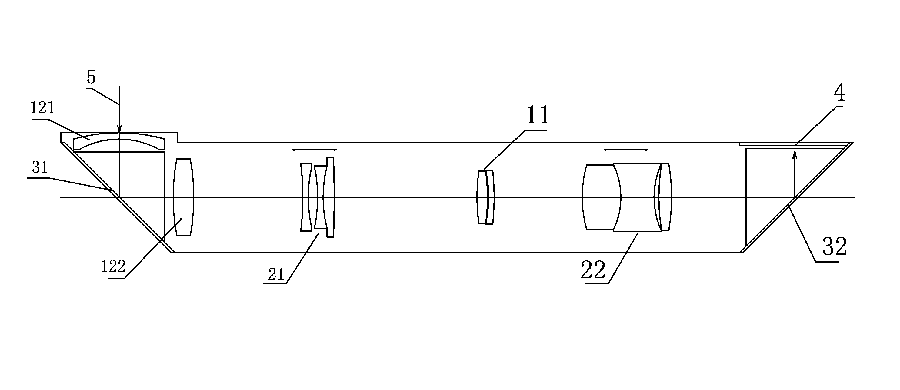
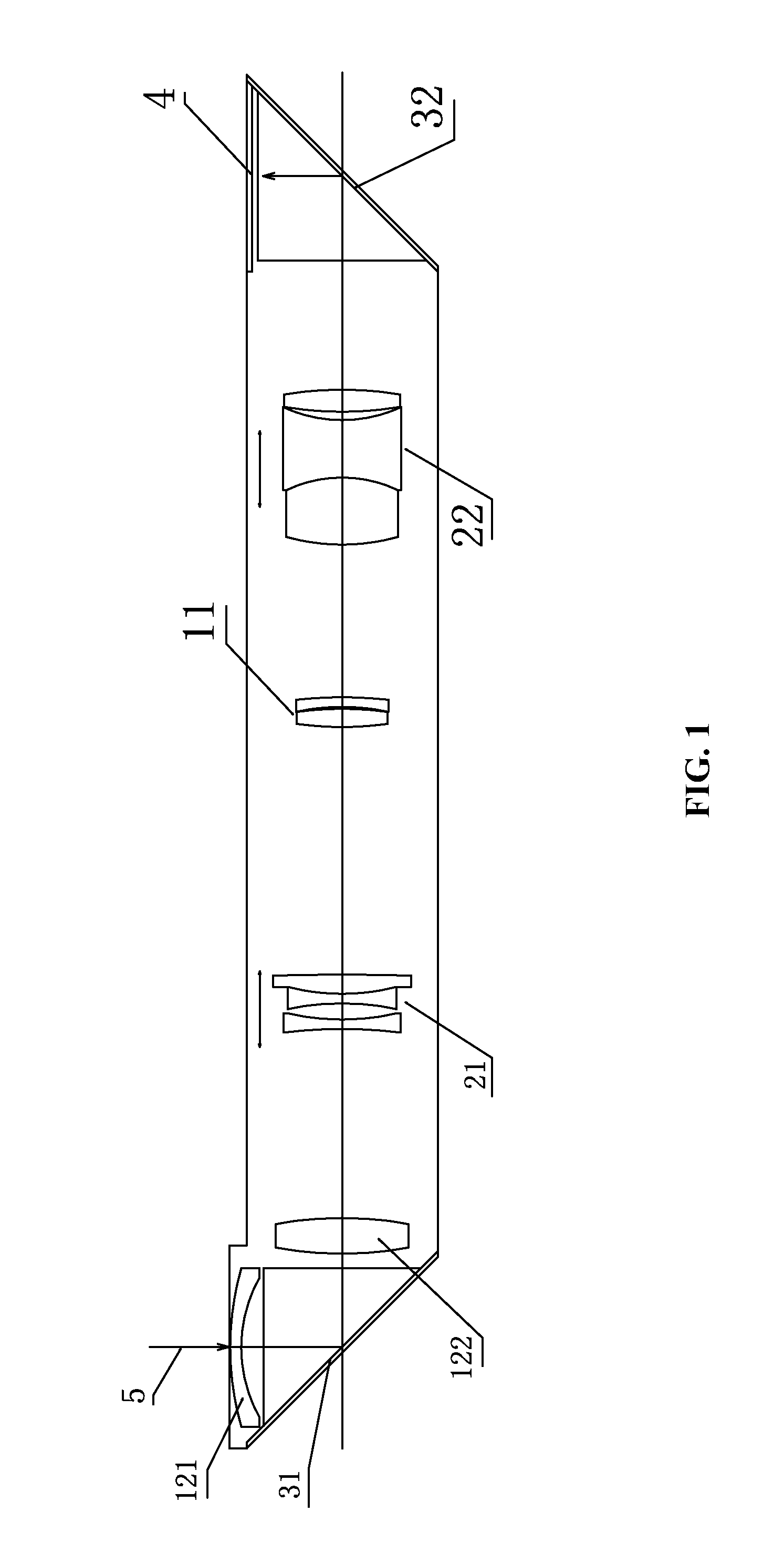
[0028]As shown in FIG. 1, an incident ray 5 is refracted by the first lens 121 of the second fixed lens group, and then reflected by the first reflective optical element at the object space. The reflecting angle is 45°. The ray passes through in order the second lens 122 of the second fixed lens group, the first movable zoom lens group 21, the first fixed lens group 11, and the second movable zoom lens group 22, and is finally reflected by the second reflective optical element 32 with an reflecting angle of 45°. The reflection ray is parallel to the original incident ray and reflected upwards on the imaging surface for imaging.
[0029]In the optical imaging system, the first movable zoom lens group 21 and the second movable zoom lens group 22 are driven by a driving mechanism to move on the optical axis whereby achieving the zooming of the optical system. When the first movable zoom lens group 21 moves towards the object space, the focal distance decreases; when the first movable zoom...
example 2
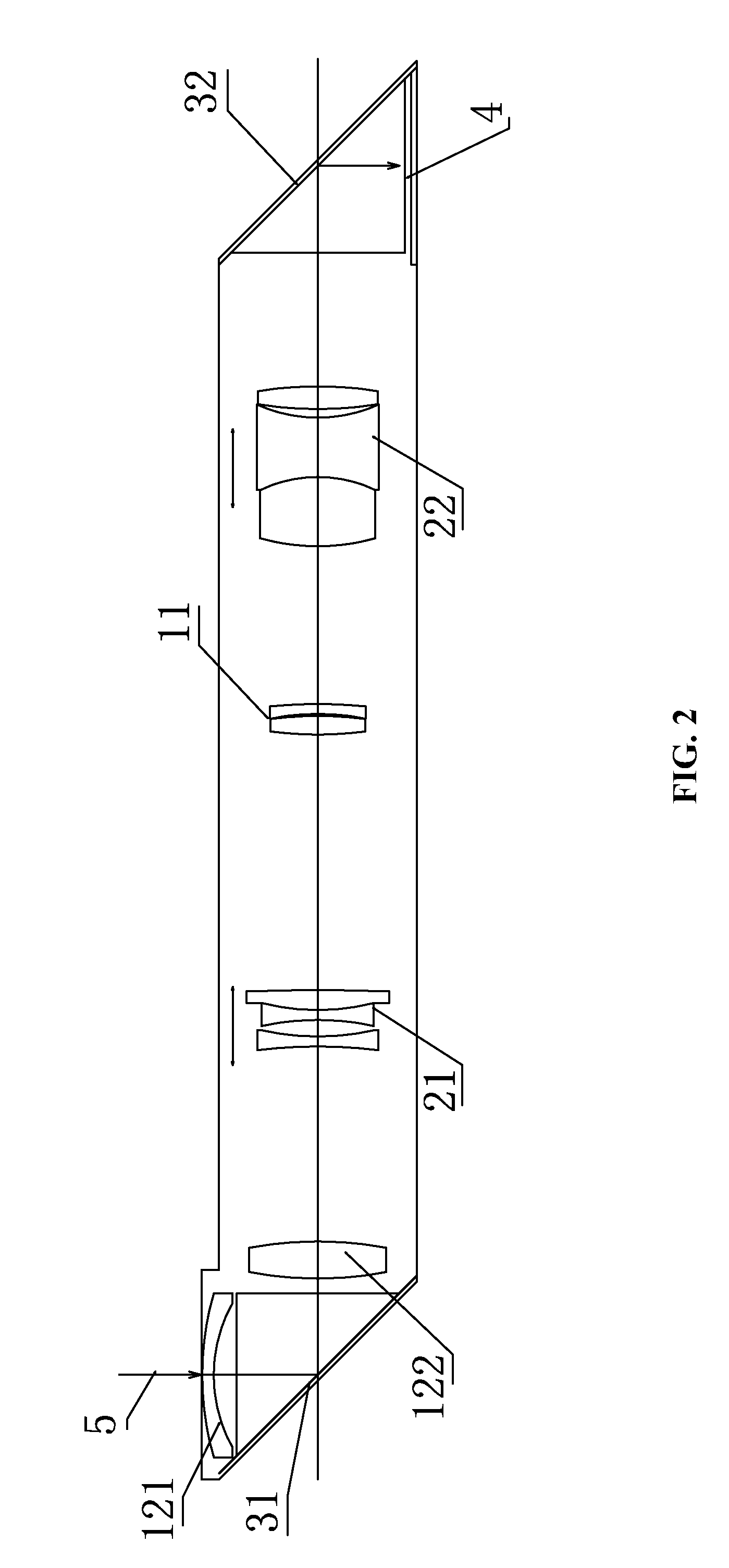
[0030]As shown in FIG. 2, an incident ray 5 is refracted by the first lens 121 of the second fixed lens group, and then reflected by the first reflective optical element at the object space. The reflecting angle is 45°. The ray passes through in order the second lens 122 of the second fixed lens group, the first movable zoom lens group 21, the first fixed lens group 11, and the second movable zoom lens group 22, and is finally reflected by the second reflective optical element 32 with an reflecting angle of 45°. The reflection ray is parallel to the original incident ray and reflected downwards on the imaging surface for imaging.
[0031]In the optical imaging system, the first movable zoom lens group 21 and the second movable zoom lens group 22 are driven by a driving mechanism to move on the optical axis whereby achieving the zooming of the optical system. When the first movable zoom lens group 21 moves towards the object space, the focal distance decreases; when the first movable zo...
PUM
 Abstract
Description
Claims
Application Information