
Method and device for positioning a brushless electric drive

a brushless electric drive and positioning technology, applied in the field of electric drives and brushless drives, can solve problems such as special problems that are difficult to solve, and achieve the effect of reliable and rapid at-rest positioning of brushless electric drives

Active Publication Date: 2016-10-18
BROSE FAHRZEUGTEILE GMBH & CO KG HALLSTADT (DE)
View PDF9 Cites 0 Cited by
  • Summary
  • Abstract
  • Description
  • Claims
  • Application Information

AI Technical Summary

Benefits of technology

[0010]It is therefore an object of the present invention to provide a method and a device that enable a reliable and rapid at-rest positioning of a brushless electric drive.
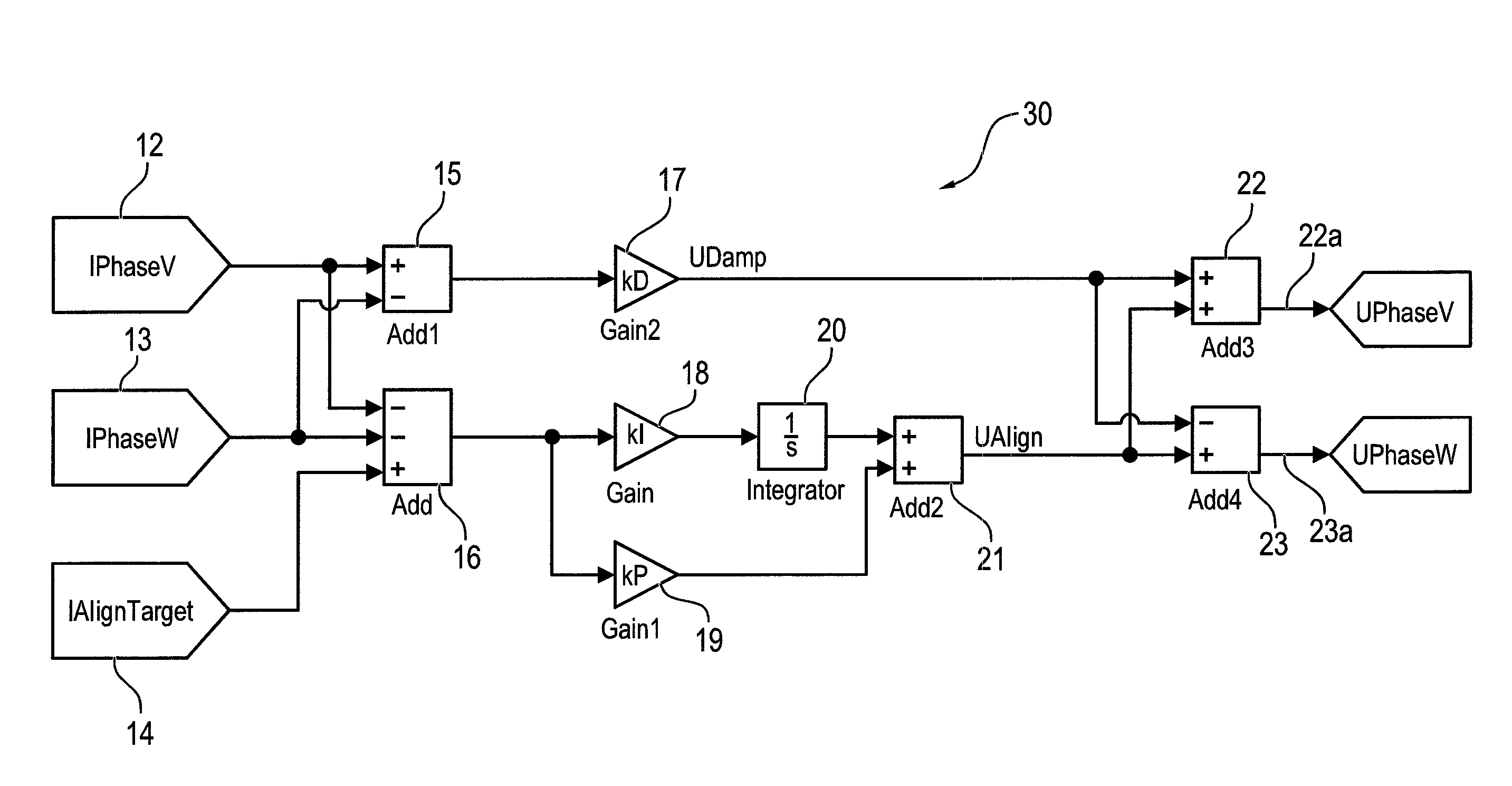
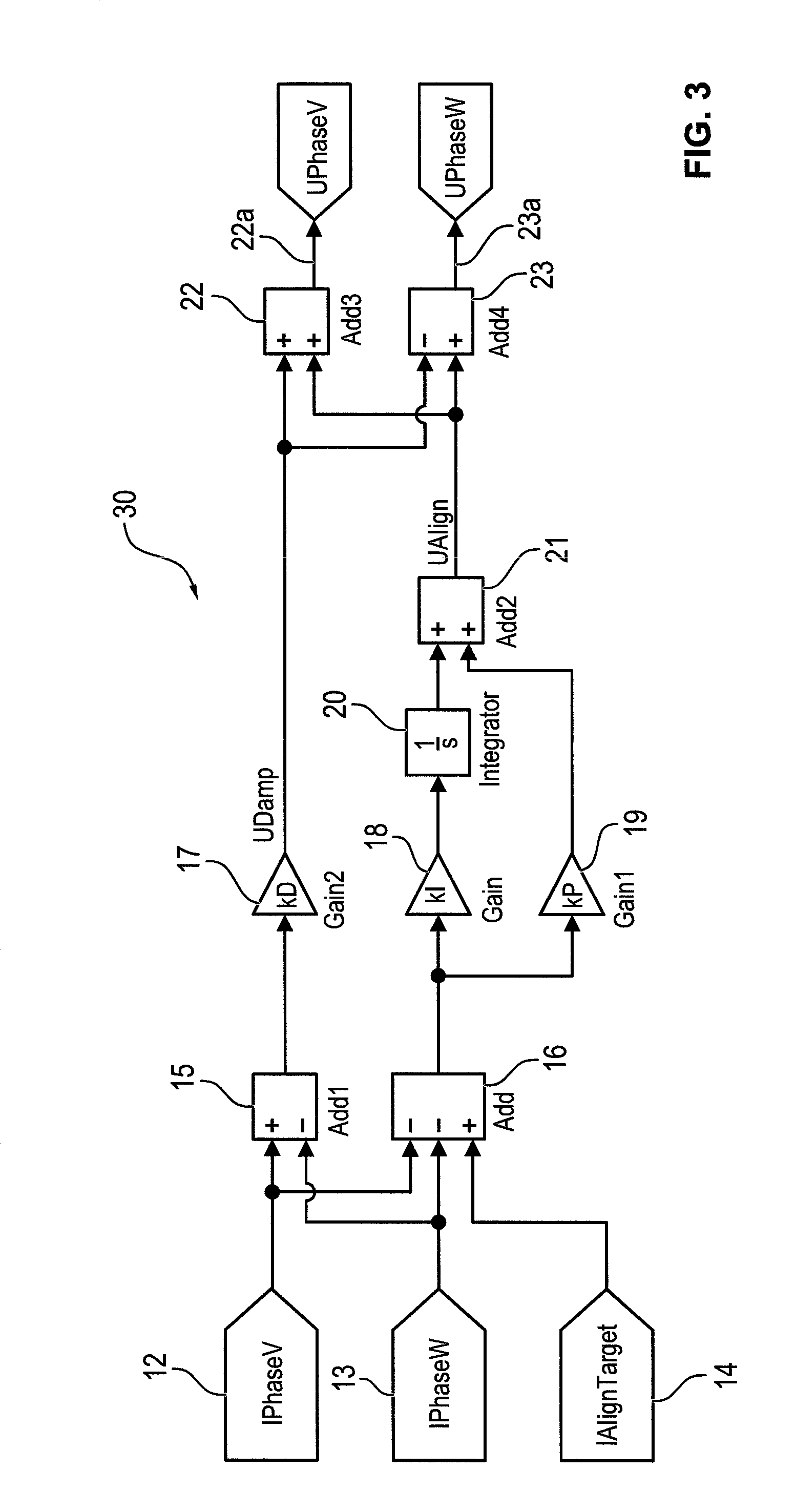
[0013]The invention is based on the realization that in the case of the basically known alignment of a drive by application of a voltage vector, the rotor continues to move in the arising stator magnetic field until it reaches a rest position, and that by the residual movement of the rotor in the phase windings a current is thereby induced, which basically works against the residual movement in a damping manner. The movement-decelerating induced currents are increased by the control of the voltage signal or a plurality of phase voltage signals as taught by the invention, so that the damping and thereby the deceleration process of the rotor movement are accelerated. Simultaneously, however, it must be assured that the current strengths in the phase windings remain within a current strength range that is still sufficient to bring about an alignment of the drive / rotor, but is not so high that a driving of the rotor is brought about.
[0015]Regulation of the sum of the current strengths in the individual phase windings assures that the magnetic fields generated by the phase windings are sufficient for aligning the drive. Because the voltages induced by the rotor's movement produce differences between the current strengths in the individual phase windings, the current strength differences are directly associated with the movement-damping, induced currents. It is desirable, therefore, to increase the differences in the current strengths in the phase windings.
[0020]In order to achieve the most rapid reaction possible of the regulation of the sum of the current strengths, it can also be provided to use a proportional controller in the regulation of the sum of the current strengths. It can be especially advantageous to use a combined proportional / integral controller.
[0022]In addition to a method for positioning a brushless electric drive, the invention also relates to a device for carrying out a method for a brushless electric drive having at least two phase windings to which a phase voltage signal can be applied. The device has a first unit for determining the sum of the current strengths through the two phase windings and a second unit for determining the difference of the current strengths through the two phase windings and a control unit, which keeps the sum of the current strengths within a target range and increases the difference of the current strengths.

Problems solved by technology

A task that is especially difficult to solve is to determine the position of the drive at very low rotational speeds or when at rest without the use of sensors and / or particularly to bring the rotor into a target start position.

Method used


Image

  • Method and device for positioning a brushless electric drive
  • Method and device for positioning a brushless electric drive
  • Method and device for positioning a brushless electric drive

Examples


Embodiment Construction

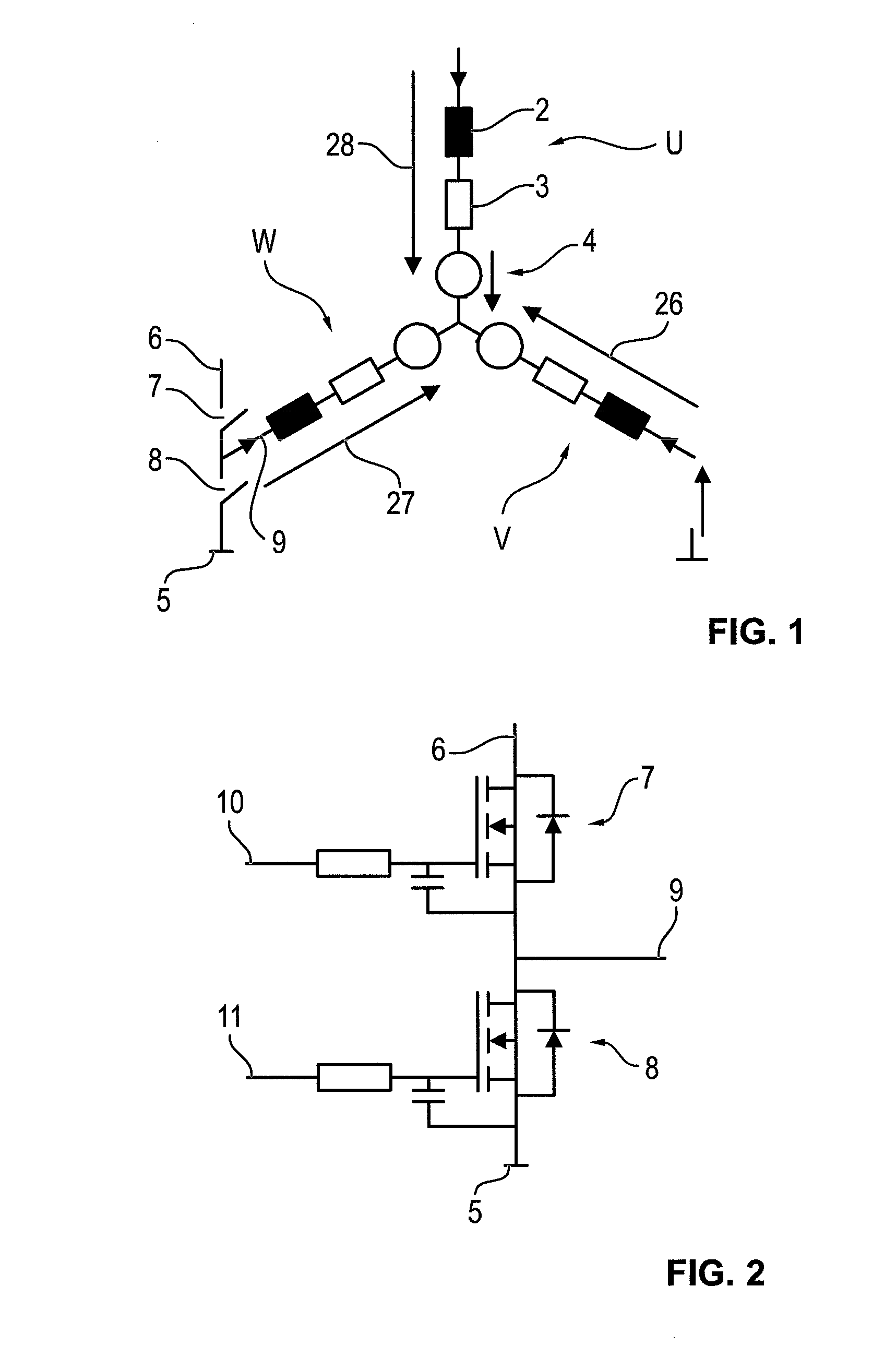
[0030]In FIG. 1, a star connection of an electric drive with three phase windings U, V, W with a neutral point 1 is shown schematically. The individual phase windings are each shown in the form of an equivalent circuit each with an inductor 2, an ohmic resistor 3, and a voltage (EMK, EMF) represented by a circle 4, which is induced by the rotor's movement. The voltage dropping across a phase winding U, V, W is represented by arrows 26, 27, 28 and arises as the sum of the voltage drops across inductor 2 and ohmic resistor 3 and the induced voltage. The overall dropping voltage 26, 27, 28 including the induced voltage in each case generates a phase current through the particular phase winding U, V, W.

[0031]This type of brushless electric drive, operated in a star connection, can be controlled via a so-called W6 connection, for example, by which in rapid time sequence a higher DC voltage level or a lower DC voltage level, particularly a ground potential, can be applied selectively to e...


PUM


Abstract

A method for positioning a brushless electric drive comprising a stator that has at least one phase winding to which a voltage signal can be applied, and a rotor equipped with magnetic poles. In the method, a voltage signal is applied to the at least one phase winding, the voltage signal generates a magnetic field as a result of the current flowing in the phase winding. The magnetic field putting the rotor into alignment, and as long as the rotor is in motion, the voltage signal is modified in accordance with the intensity of the current induced in the at least one phase winding by the moving rotor, in such a way that the induced current is increased.

Description

[0001]This nonprovisional application is a continuation of International Application No. PCT / EP2013 / 001299, which was filed on May 2, 2013, and which claims priority to German Patent Application No. DE 10 2012 008 883.3, which was filed in Germany on May 2, 2012, and which are both herein incorporated by reference.BACKGROUND OF THE INVENTION[0002]1. Field of the Invention[0003]The present invention relates to the field of electrotechnology, especially the field of electric drives, and concerns brushless drives.[0004]2. Description of the Background Art[0005]Electric motors, in which a rotor rotates in the magnetic field of a stator, whereby the rotor has rotor windings that can be supplied with alternating current strengths to excite a rotor field, are widespread in the field of electric drives. The electric current is supplied to the rotor windings via an electromechanical commutator device with current-conducting brushes, which brush the rotor-side commutator lamellae during the r...

Claims


Application Information

Patent Timeline
Patent Type & Authority Patents(United States)
IPC IPC(8): H02K29/10H02P6/00H02P6/20H02P6/24
CPCH02P6/24H02P6/28H02P6/20
Inventor SCHWARZKOPF, JOHANNES
Owner BROSE FAHRZEUGTEILE GMBH & CO KG HALLSTADT (DE)
Learn More