Method and device for positioning a brushless electric drive
- Summary
- Abstract
- Description
- Claims
- Application Information
AI Technical Summary
Benefits of technology
Problems solved by technology
Method used
Image
Examples
Embodiment Construction
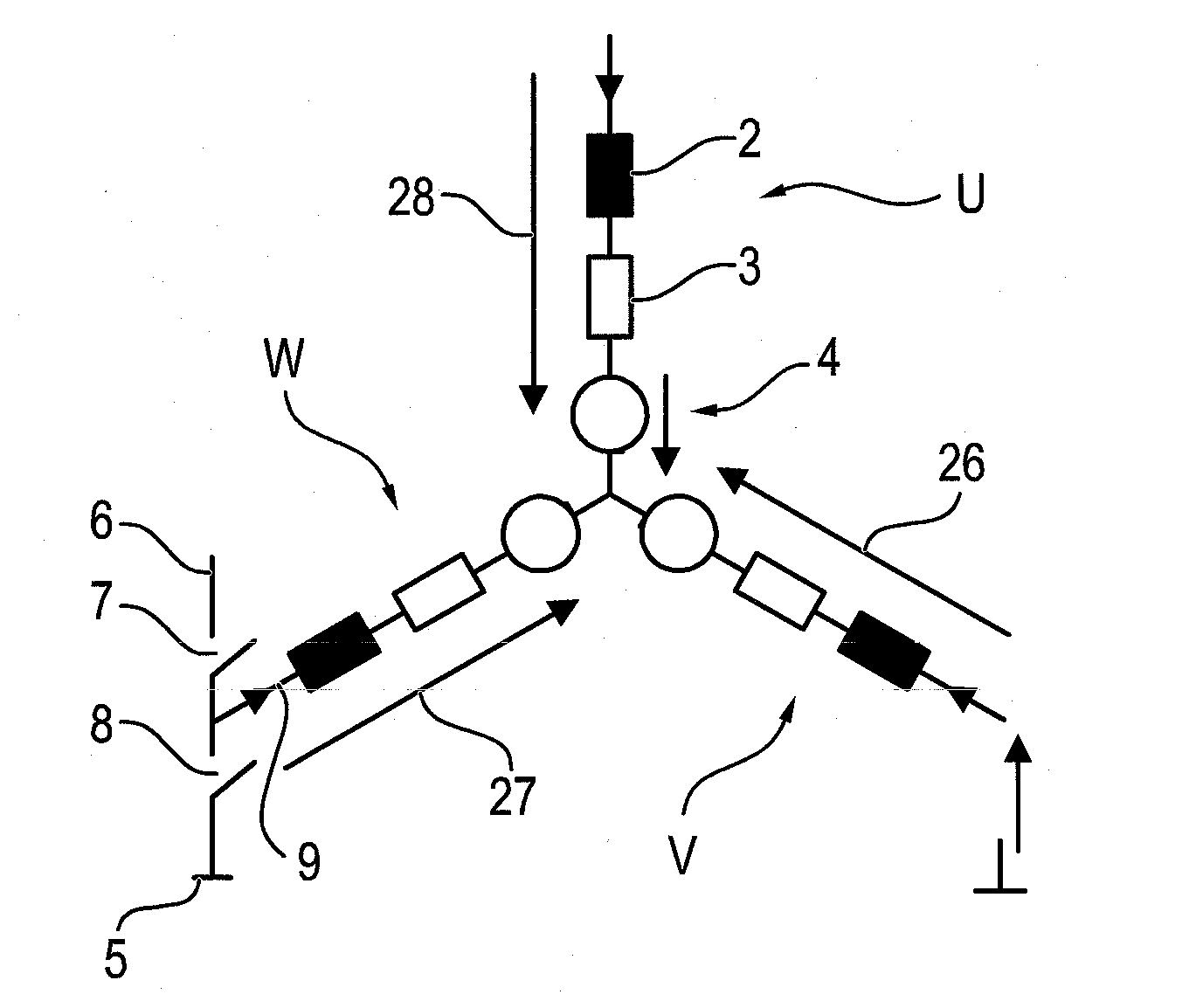
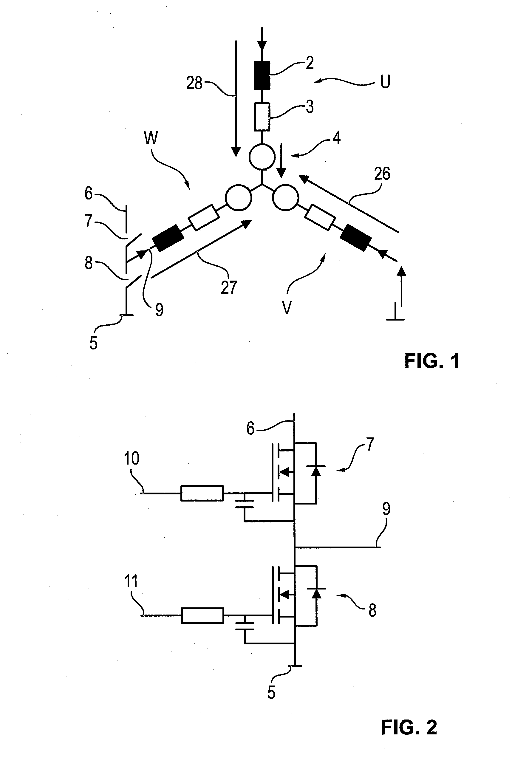
[0030]In FIG. 1, a star connection of an electric drive with three phase windings U, V, W with a neutral point 1 is shown schematically. The individual phase windings are each shown in the form of an equivalent circuit each with an inductor 2, an ohmic resistor 3, and a voltage (EMK, EMF) represented by a circle 4, which is induced by the rotor's movement. The voltage dropping across a phase winding U, V, W is represented by arrows 26, 27, 28 and arises as the sum of the voltage drops across inductor 2 and ohmic resistor 3 and the induced voltage. The overall dropping voltage 26, 27, 28 including the induced voltage in each case generates a phase current through the particular phase winding U, V, W.
[0031]This type of brushless electric drive, operated in a star connection, can be controlled via a so-called W6 connection, for example, by which in rapid time sequence a higher DC voltage level or a lower DC voltage level, particularly a ground potential, can be applied selectively to e...
PUM
 Abstract
Description
Claims
Application Information
 - R&D
- Intellectual Property
- Life Sciences
- Materials
- Tech Scout
- Unparalleled Data Quality
- Higher Quality Content
- 60% Fewer Hallucinations
Browse by: Latest US Patents, China's latest patents, Technical Efficacy Thesaurus, Application Domain, Technology Topic, Popular Technical Reports.
© 2025 PatSnap. All rights reserved.Legal|Privacy policy|Modern Slavery Act Transparency Statement|Sitemap|About US| Contact US: help@patsnap.com


