
Vehicle powered sweeper/edger device

Active Publication Date: 2016-10-25
CRUMMEY GLENN DEWIGHT
View PDF1 Cites 0 Cited by
  • Summary
  • Abstract
  • Description
  • Claims
  • Application Information

AI Technical Summary

Benefits of technology

The invention is a special sidewalk sweeper and edger that is powered by hydraulics and can be pushed by a small vehicle. It is designed for commercial industrial and municipal applications. This device allows a single operator to simultaneously edge sidewalks and remove grass and soil debris from the walkways.

Problems solved by technology

Most commercial edgers are highly labor intensive requiring a user to operate a machine in a slow, deliberate fashion (or in some cases accomplished entirely manually).
However, edging and cleanup have remained tedious and commercially expensive affairs that typically require multiple employees and valuable labor hours.

Method used


Image

  • Vehicle powered sweeper/edger device
  • Vehicle powered sweeper/edger device
  • Vehicle powered sweeper/edger device

Examples


Embodiment Construction

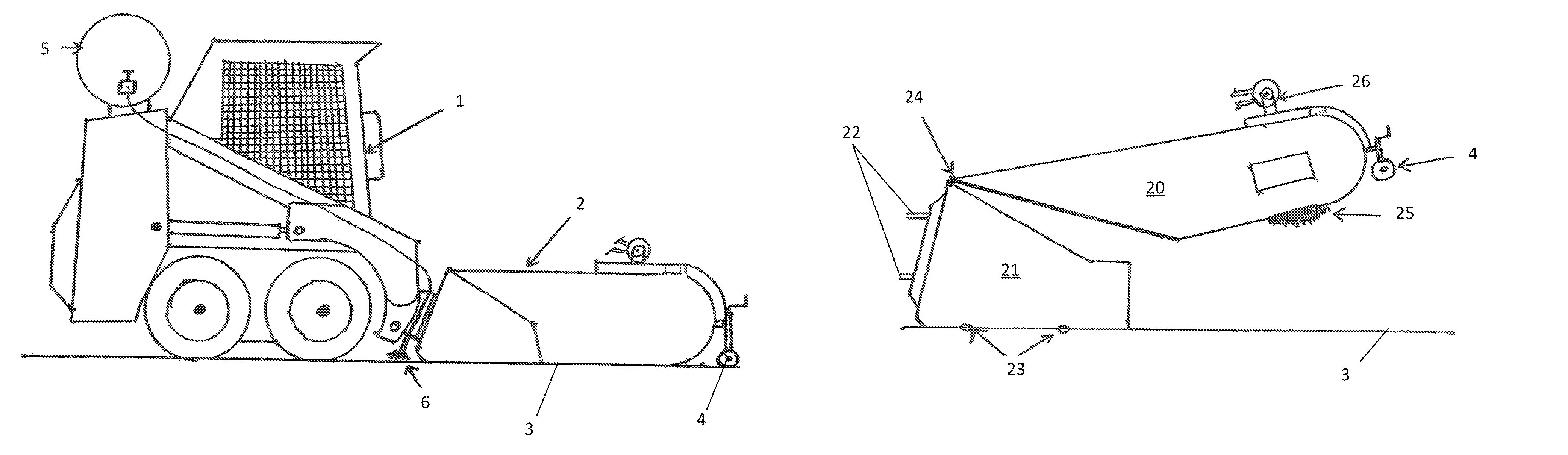
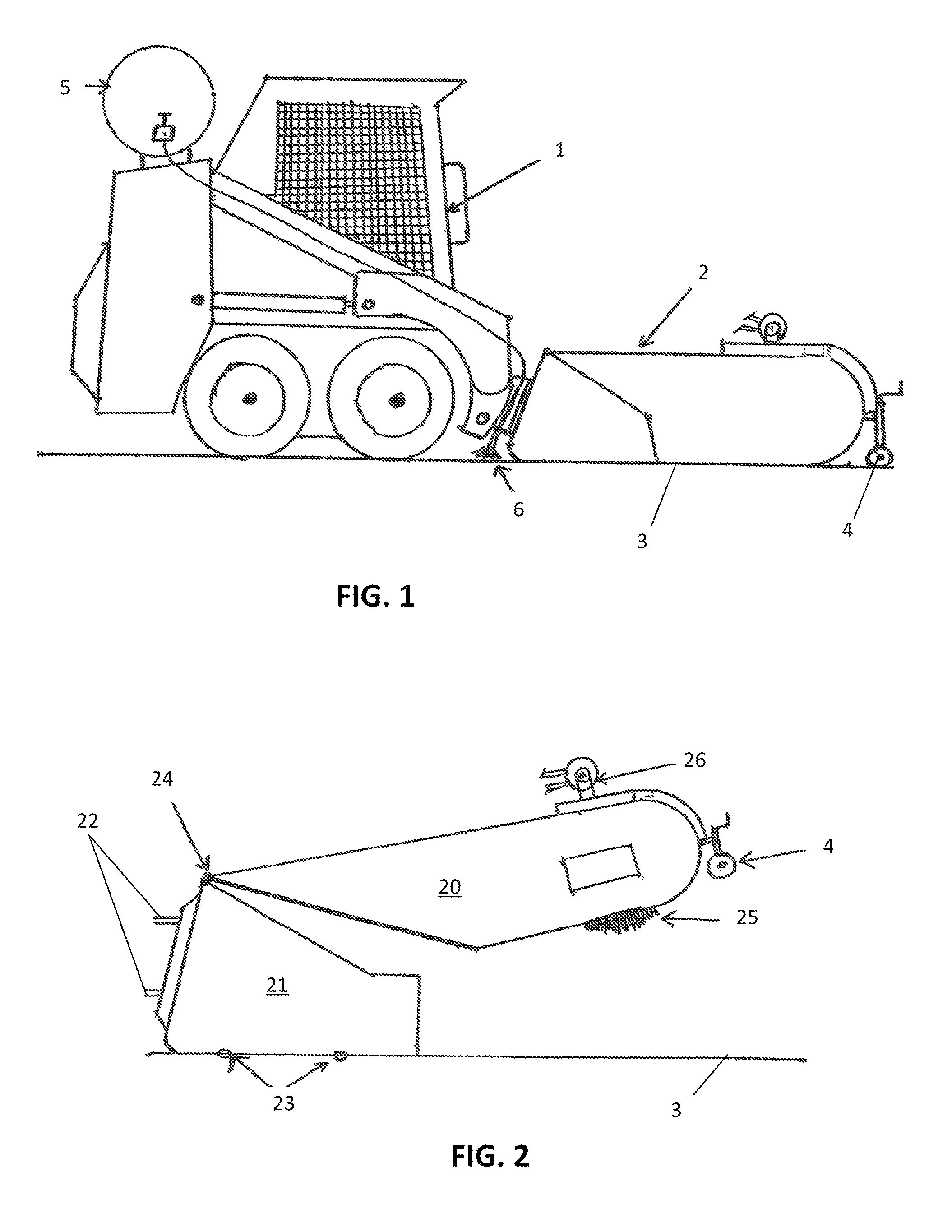
[0020]The basic hydraulically-powered sidewalk sweeper is a device composed of two articulating housings. The rear housing is mounted to the power unit and is used to collect the grass and debris thrown from the front housing's brushes. The front housing contains the sweeping and cutting brushes and is designed to “float” independent of the rear housing. These housings operate in such a fashion that when the unit is lowered to the sidewalk, the brushes sweep dirt and debris back into the rear area where it will be dumped when full into a truck or to a designated site.

[0021]Referring now to the drawings, in which like reference numerals refer to like parts in the various figures, FIG. 1 is a side view of the invention, a modification of the aforementioned basic sweeper, being pushed by a power unit. The power unit 1 shown here is a Bobcat G series skid steer loader or equivalent. It is shown pushing the preferred embodiment of the invention, a sweeper / edger device 2, along a sidewalk...


PUM


Abstract

A vehicle-powered sweeper / edger for sidewalks can edge either both sides of a sidewalk or only one side or curbs, track the edge path automatically, sweep and clean the sidewalk, and apply herbicide, and requires a single operator.

Description

CROSS-REFERENCES TO RELATED APPLICATIONS[0001]This is a non-provisional U.S. Patent Application claiming priority of U.S. Provisional Patent Application No. 61 / 849,609, filed Jan. 30, 2013.STATEMENT REGARDING FEDERALLY SPONSORED RESEARCH OR DEVELOPMENT[0002]Not applicable.NAMES OF THE PARTIES TO A JOINT RESEARCH AGREEMENT[0003]Not applicable.REFERENCE TO A BIOLOGICAL SEQUENCE LISTING[0004]Not applicable.BACKGROUND OF INVENTION[0005]1. Field of the Invention[0006]This invention is in the broad field of earth working, more specifically street sweepers and mowers, and most specifically, edgers. It is also in the field of abrading devices.[0007]2. Description of the Related Art[0008]Most commercial edgers are highly labor intensive requiring a user to operate a machine in a slow, deliberate fashion (or in some cases accomplished entirely manually). A commonly-used pavement edger comprises a motor-driven rotating blade guided by a wheel on the end of a hand-held shaft. With this unit and...

Claims


Application Information

Patent Timeline
IPC IPC(8): A01D34/84A01B49/04
CPCA01B49/04A01D34/84A01D43/063E01H1/045
Inventor CRUMMEY, GLENN DEWIGHT
Owner CRUMMEY GLENN DEWIGHT
Features
  • Generate Ideas
  • Intellectual Property
  • Life Sciences
  • Materials
  • Tech Scout
  • Unparalleled Data Quality
  • Higher Quality Content
  • 60% Fewer Hallucinations
Learn More