
Talonavicular joint prosthesis and its method of implantation

a technology for avicular joints and prostheses, applied in the field of surgery and orthopaedic instruments, can solve the problems of increased load distribution in adjacent joints, increased degenerative diseases, and greatly reduced motion, and achieve the effects of sufficient strength and rigidity, and minimizing the average thickness

Active Publication Date: 2016-10-25
SCHON LEW C +4
View PDF2 Cites 1 Cited by
  • Summary
  • Abstract
  • Description
  • Claims
  • Application Information

AI Technical Summary

Benefits of technology

The present invention relates to an improved talonavicular joint prosthesis and the method for preparing and insertion. The prosthesis includes talar and napular components that have an inner and outer surface with a defined average thickness. The components are designed to follow the anatomical contour of the original joint surface and minimize bone resection. The method involves surgically preparing the joint surfaces of the talus and napular bones to create a new joint space and implanting the components. The technical effect of this invention is to provide improved outcomes and minimize complications associated with replacing the natural talonavicular joint.

Problems solved by technology

Unfortunately, this method has had significant drawbacks—e.g., hindfoot motion is greatly reduced; limiting the motion in the joint results in greater load distribution in adjacent joints—which can yield further degenerative disease.
Such a surgical approach and the size of the prosthesis' components results in the resection of an inordinate amount of bone and the compromising of adjoining critical bony and soft tissue structures.
This situation has reportedly led to the diminishment over time of the stability of the orientation of the prosthesis' components and the ultimate failure of the prosthesis.

Method used


Image

  • Talonavicular joint prosthesis and its method of implantation
  • Talonavicular joint prosthesis and its method of implantation
  • Talonavicular joint prosthesis and its method of implantation

Examples


Embodiment Construction

[0031]Before explaining at least one embodiment of the present invention in detail, it is to be understood that the invention is not limited in its application to the details of the components set forth in the following description or illustrated in the drawings. The invention is capable of other embodiments and of being practiced and carried out in various ways. Also, it is to be understood that the phraseology and terminology employed herein are for the purpose of description and should not be regarded as limiting.

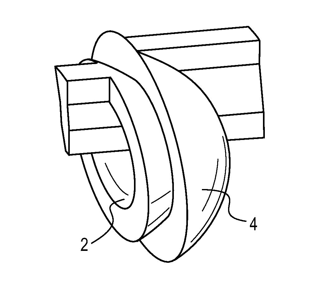
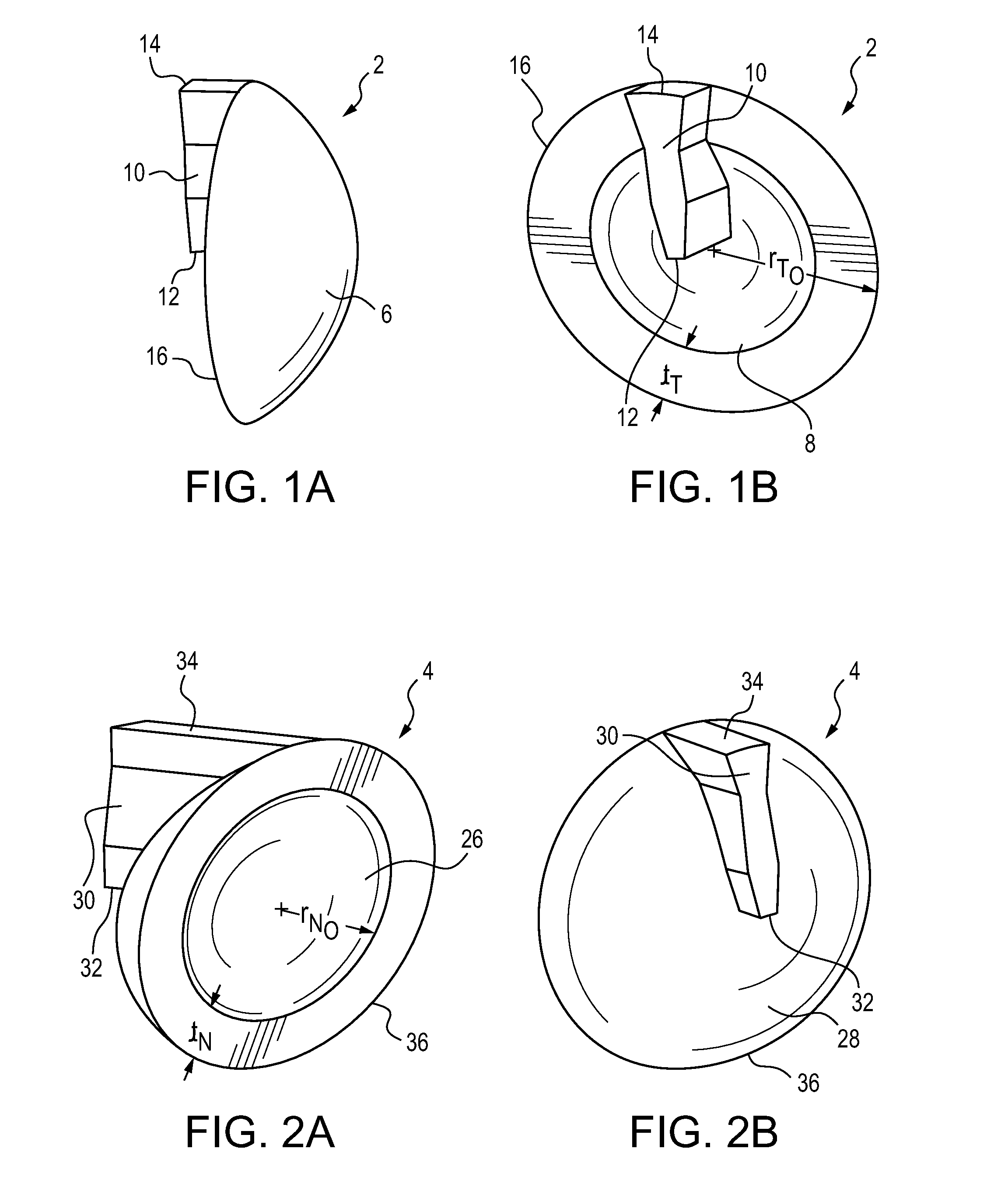
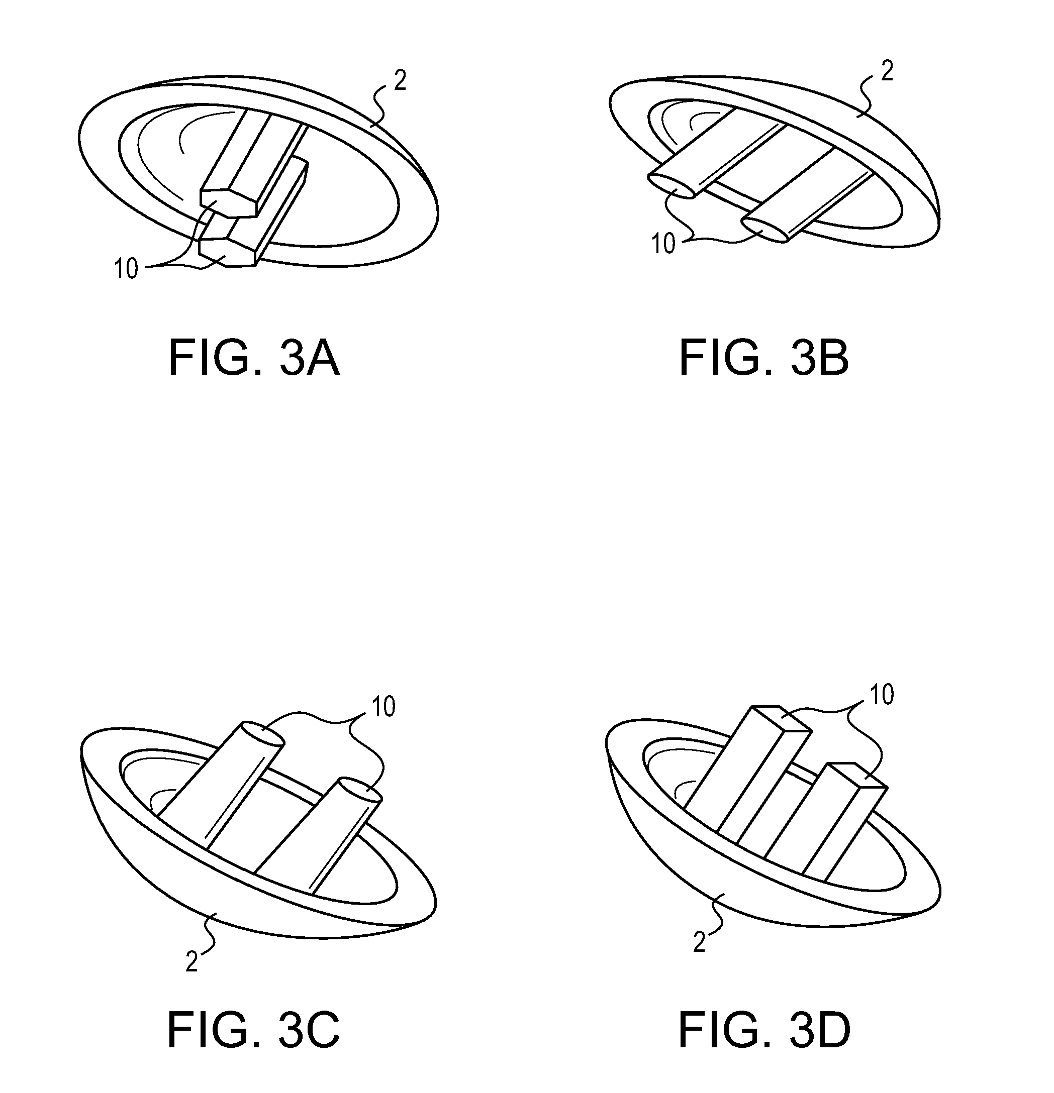
[0032]In the preferred embodiment, the talonavicular joint prosthesis 1 of the present invention includes talar 2 and navicular 4 components. See FIGS. 1A-1B and 2A-2B. These components are designed so as to permit a patient who has such a prosthesis implanted to have normal, physiologic hindfoot motion, including rotation and translation in the rear or hind-part of the foot, i.e., the talonavicular joint prosthesis of the present invention reproduces natural talonavicul...


PUM


Abstract

A talonavicular joint prosthesis (1) adapted to replace the natural talonavicular joint that exists between a patient's talus and navicular bones, after appropriate surgical preparation of the joint-related portions of these bones so as to create a new joint space to accommodate this prosthesis, includes talar (2) and navicular (4) components. Each of these have inner (8, 28) and outer (6, 26) surfaces whose average separate distance is defined as the component's average thickness. These components inner (8, 28) surfaces are configured to: (a) generally follow the anatomic contour of the original joint surface to which each component is to be attached, and (b) minimize each component's average thickness, consistent with providing sufficient strength and rigidity for the components, so as to require minimum bone resection in the creation of the new prosthesis-accommodating, joint space.

Description

CROSS-REFERENCE TO RELATED APPLICATION[0001]This application claims the benefit of PCT Patent Application No. PCT / US2010 / 002429, filed Sep. 4, 2010 by the present inventors. The teachings of this application are incorporated herein by reference to the extent that they do not conflict with the teaching herein.BACKGROUND OF THE INVENTION[0002]1. Field of the Invention[0003]This invention relates to surgery and orthopaedic instrumentation. More particularly, this invention relates to a talonavicular joint prosthesis and the surgical procedure and apparatus for its implantation.[0004]2. Description of the Related Art[0005]The talonavicular joint is comprised of the articulation between the talus and navicular bones. For many years, one of the more aggressive methods for treating diseased or injured talonavicular joints was a fusion between the talus and navicular bones. Unfortunately, this method has had significant drawbacks—e.g., hindfoot motion is greatly reduced; limiting the motion...

Claims


Application Information

Patent Timeline
Patent Type & Authority Patents(United States)
IPC IPC(8): A61F2/42A61B17/16A61F2/30
CPCA61F2/4202A61B17/1682A61B17/1615A61F2002/3021A61F2002/30143A61F2002/30182A61F2002/30224A61F2002/30247A61F2002/30263A61F2002/30268A61F2002/30332A61F2002/30354A61F2002/30538A61F2002/30738A61F2002/30878A61F2002/30884A61F2002/30892A61F2002/422A61F2002/4207A61F2002/30261A61F2002/30245
Inventor SCHON, LEW C.CHIODO, CHRISTOPHERPARKS, BRENT G.NADAUD, JOSHDINC, ZEYNEP BUSRA
Owner SCHON LEW C
Learn More