Ophthalmologic imaging apparatus and ophthalmologic image processing apparatus
a technology of ophthalmologic imaging and image processing, which is applied in the field of ophthalmologic imaging apparatus and ophthalmologic image processing apparatus, can solve the problems of difficult repeating the same scanning position as a past examination, difficult ophthalmology follow-up, and difficult reproducing the same scanning position as a previous examination, so as to quantitatively evaluate the degree of errors in follow-up imaging
- Summary
- Abstract
- Description
- Claims
- Application Information
AI Technical Summary
Benefits of technology
Problems solved by technology
Method used
Image
Examples
first embodiment
Configurations
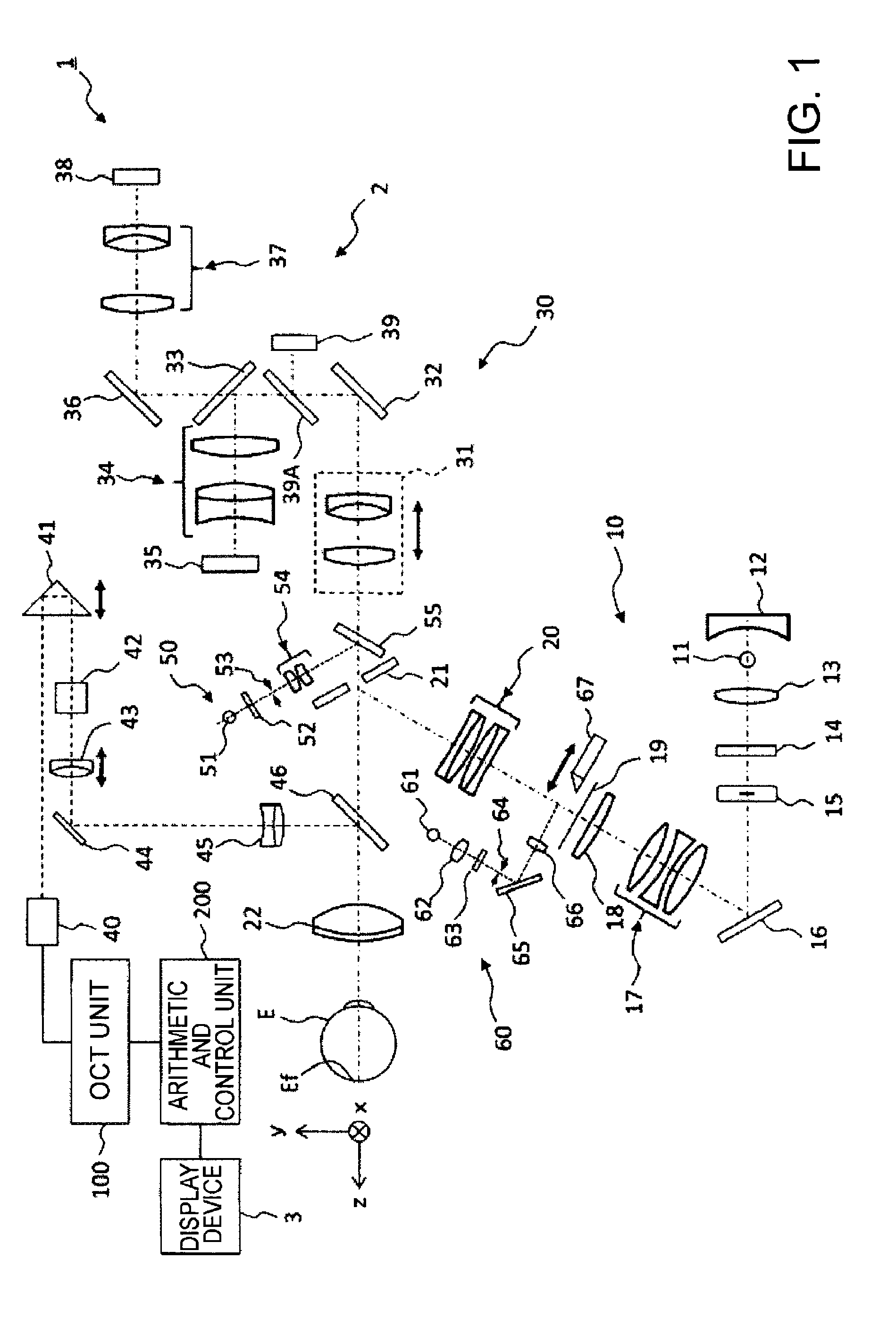
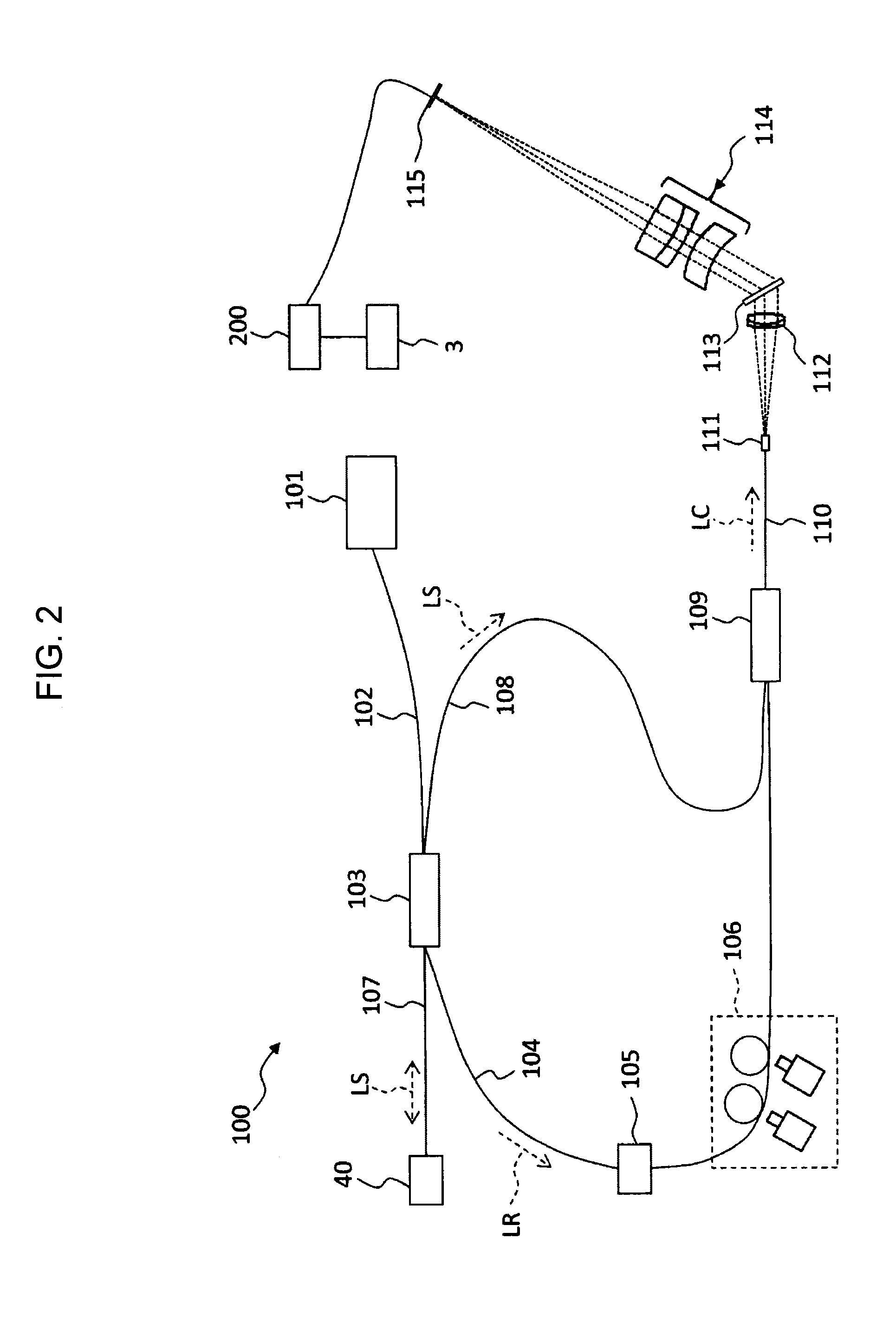
[0053]An ophthalmologic imaging apparatus 1, as shown in FIG. 1 and FIG. 2, includes a retinal camera unit 2, an OCT unit 100, and an arithmetic and control unit 200. The retinal camera unit 2 has almost the same optical system as a conventional retinal camera. The OCT unit 100 is provided with an optical system for obtaining an OCT image of a fundus. The arithmetic and control unit 200 is provided with a computer that executes various arithmetic processes, control processes, and so on.
[Retinal Camera Unit]
[0054]The retinal camera unit 2 shown in FIG. 1 is provided with an optical system for forming a 2-dimensional image (fundus image) representing the surface morphology of the fundus Ef of an eye E. Fundus images include observation images, photographed images, etc. The observation image is, for example, a monochromatic moving image formed at a prescribed frame rate using near-infrared light. The photographed image may be, for example, a color image captured by flashi...
second embodiment
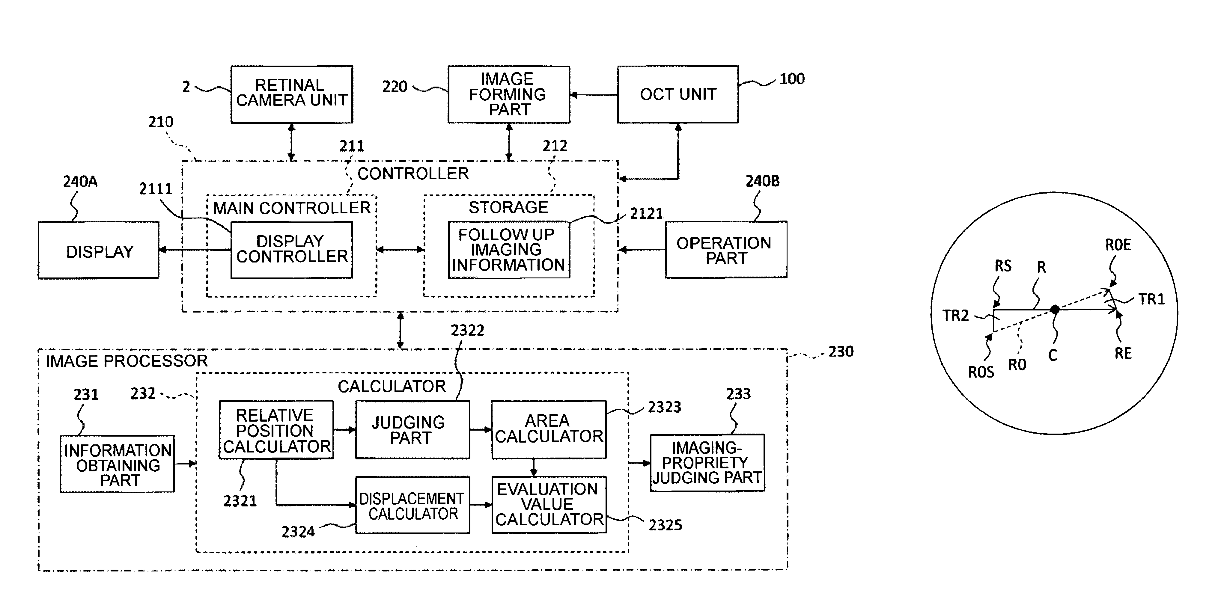
[0172]Follow up imaging is carried out by referring to a reference front image acquired in the past. So, accuracy and precision of follow up imaging are influenced by the condition of the reference front image. In the present embodiment, an ophthalmologic imaging apparatus, in addition to arbitrary configuration described in the first embodiment, capable of judging propriety of a reference front image used in follow up imaging is described.
[0173]FIG. 9 illustrates a configuration example of the ophthalmologic imaging apparatus according to the present embodiment. The ophthalmologic imaging apparatus includes a candidate image judging part 234 in addition to the configuration of the first embodiment (see FIGS. 1 to 4). The candidate image judging part 234 is provided in the image processor 230. It should be noted that descriptions of configurations other than the candidate image judging part 234 are omitted unless otherwise stated since they are the same as the first embodiment.
[0174...
third embodiment
[0188]The present embodiment describes an ophthalmologic image processing apparatus that receives information from an ophthalmologic imaging apparatus capable of carrying out follow up imaging and processes the received information. The ophthalmologic image processing apparatus is configured to include a computer, for example. Further, part of the ophthalmologic image processing apparatus may be arranged outside a computer. For example, storage may be a database on a network.
[0189]FIG. 11 illustrates a configuration example of an ophthalmologic image processing apparatus of the present embodiment. This ophthalmologic image processing apparatus includes a configuration similar to the first embodiment (see FIG. 4). On the other hand, this ophthalmologic image processing apparatus does not include the photographing part (retinal camera unit 2) and the cross sectional image forming part (optical system for OCT measurement and the image forming part 220). Further, the ophthalmologic imag...
PUM
 Abstract
Description
Claims
Application Information
 - R&D
- Intellectual Property
- Life Sciences
- Materials
- Tech Scout
- Unparalleled Data Quality
- Higher Quality Content
- 60% Fewer Hallucinations
Browse by: Latest US Patents, China's latest patents, Technical Efficacy Thesaurus, Application Domain, Technology Topic, Popular Technical Reports.
© 2025 PatSnap. All rights reserved.Legal|Privacy policy|Modern Slavery Act Transparency Statement|Sitemap|About US| Contact US: help@patsnap.com


