Ophthalmologic imaging apparatus and ophthalmologic image processing apparatus

a technology of ophthalmologic imaging and image processing, which is applied in the field of ophthalmologic imaging apparatus and ophthalmologic image processing apparatus, can solve the problems of difficult repeating the same scanning position as a past examination, difficult ophthalmology follow-up, and difficult reproducing the same scanning position as a previous examination, so as to quantitatively evaluate the degree of errors in follow-up imaging

Active Publication Date: 2015-05-21
KK TOPCON
View PDF1 Cites 11 Cited by
  • Summary
  • Abstract
  • Description
  • Claims
  • Application Information

AI Technical Summary

Benefits of technology

[0055]According to the present invention, it is possible to quantitatively evaluate degrees of errors in follow up imaging.

Problems solved by technology

There are specific problems in ophthalmology regarding follow up.
Specifically, it is difficult to examine a same site repeatedly because of influences of eye movement (involuntary eye movement during fixation, rotation, etc.) of a subject eye.
In particular, reproducing the same scanning position as a past examination is extremely difficult for an imaging apparatus of the type that scans an eye with light.

Method used


Image

  • Ophthalmologic imaging apparatus and ophthalmologic image processing apparatus
  • Ophthalmologic imaging apparatus and ophthalmologic image processing apparatus
  • Ophthalmologic imaging apparatus and ophthalmologic image processing apparatus

Examples


first embodiment

Configurations

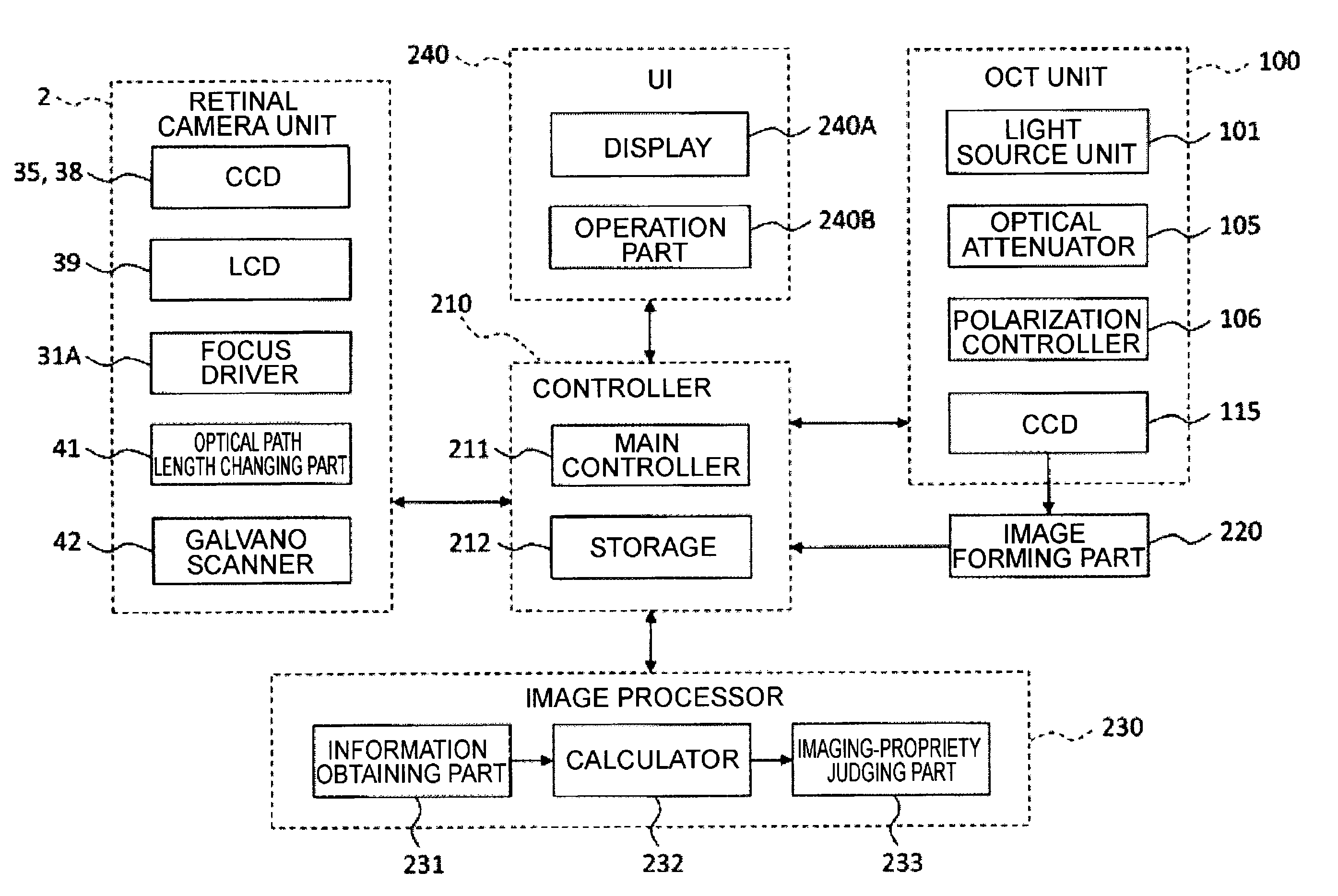
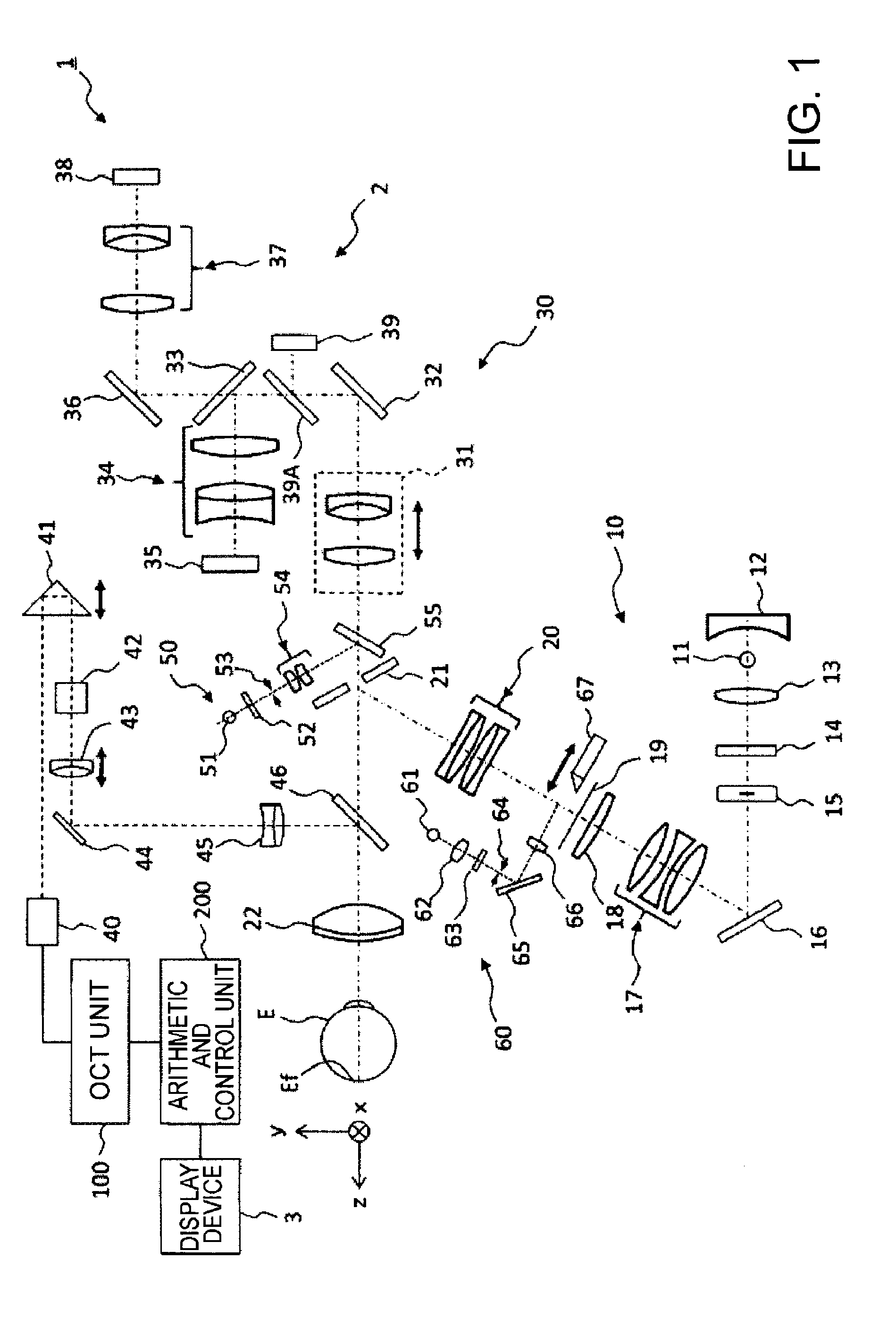
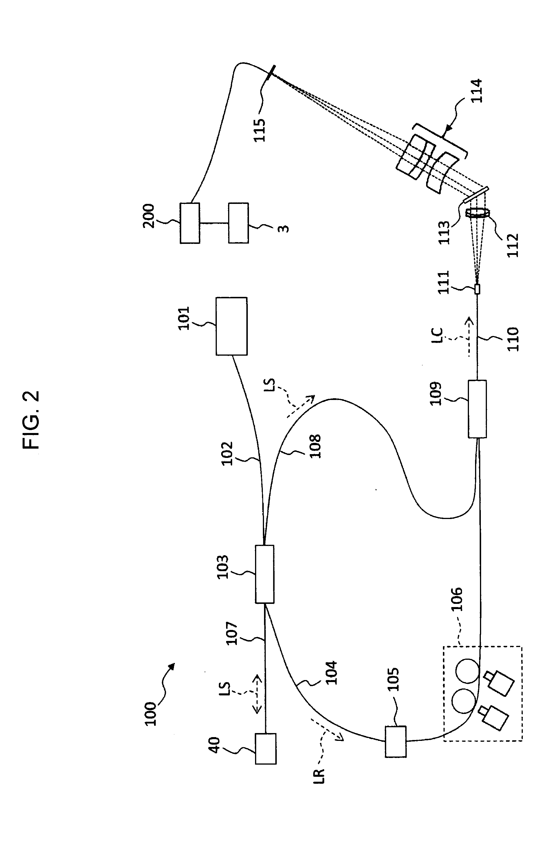
[0077]An ophthalmologic imaging apparatus 1, as shown in FIG. 1 and FIG. 2, includes a retinal camera unit 2, an OCT unit 100, and an arithmetic and control unit 200. The retinal camera unit 2 has almost the same optical system as a conventional retinal camera. The OCT unit 100 is provided with an optical system for obtaining an OCT image of a fundus. The arithmetic and control unit 200 is provided with a computer that executes various arithmetic processes, control processes, and so on.

[Retinal Camera Unit]

[0078]The retinal camera unit 2 shown in FIG. 1 is provided with an optical system for forming a 2-dimensional image (fundus image) representing the surface morphology of the fundus Ef of an eye E. Fundus images include observation images, photographed images, etc. The observation image is, for example, a monochromatic moving image formed at a prescribed frame rate using near-infrared light. The photographed image may be, for example, a color image captured by flashi...

second embodiment

[0196]Follow up imaging is carried out by referring to a reference front image acquired in the past. So, accuracy and precision of follow up imaging are influenced by the condition of the reference front image. In the present embodiment, an ophthalmologic imaging apparatus, in addition to arbitrary configuration described in the first embodiment, capable of judging propriety of a reference front image used in follow up imaging is described.

[0197]FIG. 9 illustrates a configuration example of the ophthalmologic imaging apparatus according to the present embodiment. The ophthalmologic imaging apparatus includes a candidate image judging part 234 in addition to the configuration of the first embodiment (see FIGS. 1 to 4). The candidate image judging part 234 is provided in the image processor 230. It should be noted that descriptions of configurations other than the candidate image judging part 234 are omitted unless otherwise stated since they are the same as the first embodiment.

[0198...

third embodiment

[0212]The present embodiment describes an ophthalmologic image processing apparatus that receives information from an ophthalmologic imaging apparatus capable of carrying out follow up imaging and processes the received information. The ophthalmologic image processing apparatus is configured to include a computer, for example. Further, part of the ophthalmologic image processing apparatus may be arranged outside a computer. For example, storage may be a database on a network.

[0213]FIG. 11 illustrates a configuration example of an ophthalmologic image processing apparatus of the present embodiment. This ophthalmologic image processing apparatus includes a configuration similar to the first embodiment (see FIG. 4). On the other hand, this ophthalmologic image processing apparatus does not include the photographing part (retinal camera unit 2) and the cross sectional image forming part (optical system for OCT measurement and the image forming part 220). Further, the ophthalmologic imag...


PUM


Abstract

An ophthalmologic imaging apparatus that can follow up imaging for acquiring a cross sectional image by referring to a front image of an eye acquired in the past and scanning the same position as before with light, includes: a photographing part configured to photograph the eye and acquire a front image thereof; a cross sectional image forming part configured to scan the eye with light and form a cross sectional image thereof; a storage configured to store a first front image of the eye and a second front image acquired in follow up imaging executed with referring to the first front image; an information obtaining part configured to analyze the first and second front images and obtain misregistration information between these front images; and a calculator configured to calculate an evaluation value of an error in a scanning position in the follow up imaging based on the misregistration information.

Description

TECHNICAL FIELD[0001]The present invention relates to an ophthalmologic imaging apparatus and an ophthalmologic image processing apparatus.BACKGROUND TECHNOLOGY[0002]In recent years, optical coherence tomography (OCT) has attracted attention as an apparatus for imaging an eye using optical scanning. Unlike an X-ray CT apparatus, optical coherence tomography is noninvasive to human bodies, and is therefore expected to be utilized in the medical field and biological field. For example, in the ophthalmology, apparatuses that form images of a fundus and cornea or the like are in a practical stage.[0003]The apparatus disclosed in Patent Document 1 uses a technique of so-called “Fourier Domain OCT.” That is to say, the apparatus irradiates a low-coherence light beam to an object, superposes the reflected light and the reference light to generate an interference light, and acquires the spectral intensity distribution of the interference light to execute Fourier transform, thereby imaging t...

Claims


Application Information

Patent Timeline
Patent Type & Authority Applications(United States)
IPC IPC(8): A61B3/00A61B3/10A61B3/14
CPCA61B3/0025A61B3/0058A61B3/102A61B3/14A61B3/10F04C2270/041
Inventor MORIGUCHI, YOSHIKIYOAKIBA, MASAHIRO
Owner KK TOPCON
Why Eureka
Try Eureka