Shield wire

a shield wire and wire technology, applied in the direction of power cables, cables, coupling device connections, etc., can solve the problems of insufficient contact between drain lines and metal foils, inability to obtain sufficient shield effects, and described problems, etc., to achieve the effect of simplifying processes or devices, and suppressing deformation external forms

Active Publication Date: 2016-11-15
YAZAKI CORP
View PDF34 Cites 11 Cited by
  • Summary
  • Abstract
  • Description
  • Claims
  • Application Information

AI Technical Summary

Benefits of technology

[0011]The present invention is devised by considering the above-described circumstances and it is an object of the present invention to provide a shield wire which can be lightened and can sufficiently exhibit a shielding function, suppress a deformed external form and simplify processes or a device.
[0018]According to the present invention, since the shield member having the metal foil, that is, the metal foil shield member is used, the shield member can be effectively made to be exceptionally lighter than the shield member formed with the braided wire. Further, in the present invention, since the shield wire has a structure which includes the metal foil, however, does not use the drain line, the shield wire can be effectively lightened the more for the drain line or effectively suppress the deformed external form. Further, according to the present invention, since both the end parts of the metal foil shield member are arranged in the semicircular parts as one parts of outer surfaces of the insulators in section so as to suppress the collapse of the end parts or the bound of the end parts of the metal foil shield member, the inner wire part can be effectively held and stabilized and the shielding function can be sufficiently exhibited.
[0019]Further, according to the present invention, since the metal foil shield member has the ground connecting part, the inner wire part can be effectively covered with the metal foil shield member up to the terminal of the electric wire. Thus, a sufficient shield effect can be successfully obtained in the terminal of the electric wire.
[0020]Further, according to the present invention, the shield wire for a high tension which is preferably suitable for a hybrid motor vehicle or an electric vehicle can be effectively provided.

Problems solved by technology

In the above-described usual technique, when the shield member formed with the braided wire is used, a below-described problem arises.
Further, in the above-described usual technique, when the shield member formed with the metal foil and the drain line is used, a below-described problem arises.
Thus, the problem arises that a sufficient shield effect cannot be obtained.
In addition thereto, when the shield member formed with the metal foil and the drain line is used, a below-described problem also arises.
Namely, in the shield member, when the drain line is arranged between electric wires, there is a fear that the drain line does not come into sufficient contact with the metal foil.
However, in this case, since the drain line has a thickness extremely larger than a thickness of the metal foil, the problem arises that a finished external form of a wire harness (or a cable) is the more deformed in the part of the drain line.
As for the metal foil, when an end part thereof collapses or bounds between the electric wires, a problem arises that the electric wire is unstably held, so that the shielding function cannot be sufficiently exhibited.
Further, as for the metal foil and the drain line, a problem also arises that the drain line needs to be put in the metal foil, so that processes and a device are complicated.

Method used


Image

  • Shield wire
  • Shield wire
  • Shield wire

Examples


Embodiment Construction

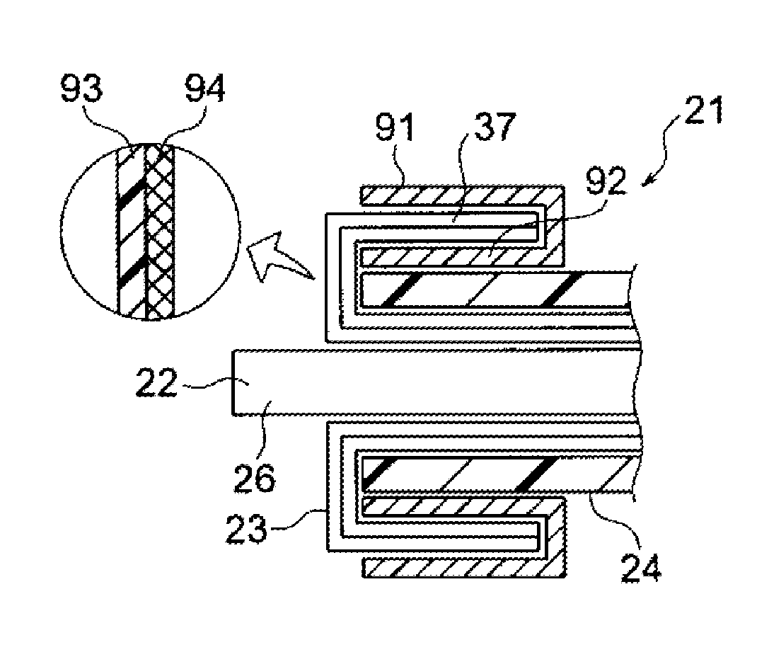
[0030]A shield wire is provided with a sheet shaped metal foil shield member so as to envelop an inner wire part having a plurality of conductors and insulators. In the shield wire, the inner wire part is enveloped by the metal foil shield member so as to hold the inner wire part so that an end part of the metal foil shield member is avoided from collapsing or bounding.

Exemplary Embodiment

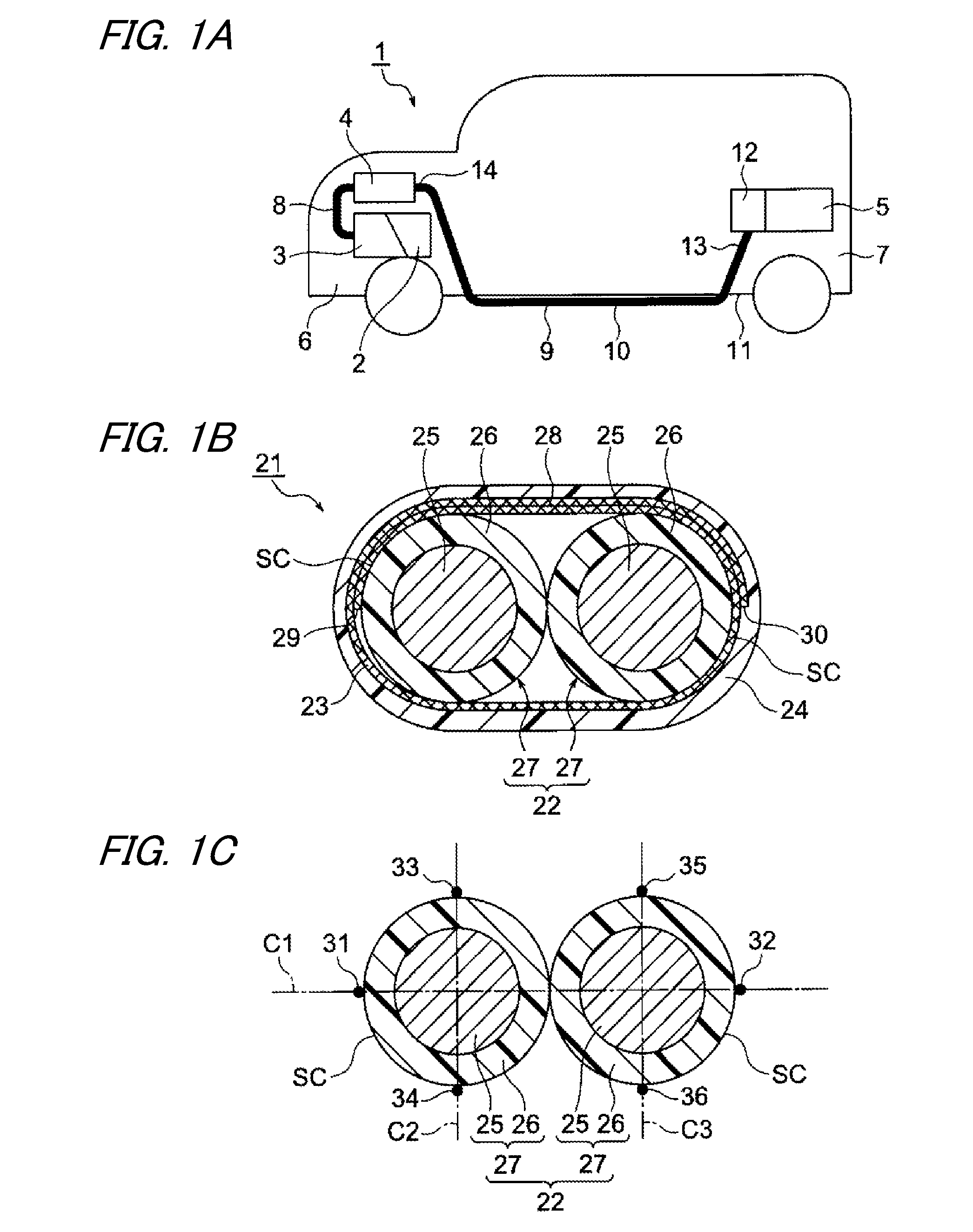
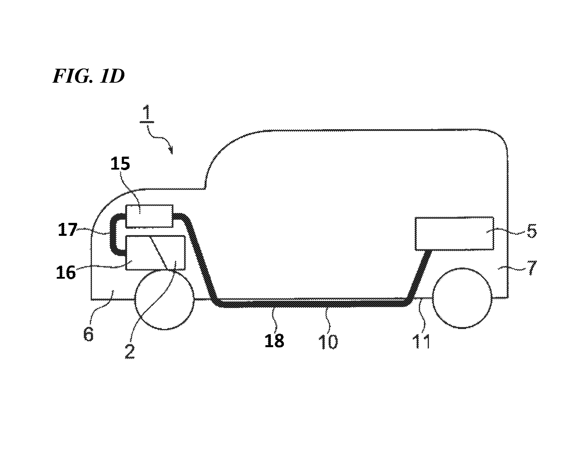
[0031]Now, an exemplary embodiment will be described below by referring to the drawings. FIG. 1A to FIG. 1C are diagrams relating to a shield wire of the present invention. FIG. 1A is a schematic view of a vehicle, FIG. 1B is a sectional view of the shield wire and FIG. 1C is a diagram showing one end and the other end positions of an inner wire part. FIG. 2A and FIG. 2B are diagrams relating to a comparison of the shield wire. FIG. 3A to FIG. 3C are schematic views relating to a manufacturing method of the shield wire. FIG. 4A to FIG. 6C are sectional views relating to other examples of the shield...


PUM

PropertyMeasurementUnit
areaaaaaaaaaaa
widthaaaaaaaaaa
tensionaaaaaaaaaa

Abstract

In a shield wire, a sheet shaped metal foil shield member is provided so as to envelop an inner wire part having a plurality of conductors and insulators. In the shield wire, the inner wire part is enveloped by the metal foil shield member so that the inner wire part is held and an end part of the metal foil shield member is avoided from collapsing or the end is avoided from bounding.

Description

CROSS REFERENCE TO RELATED APPLICATIONS[0001]This application is a continuation of PCT application No. PCT / JP2012 / 062871, which was filed on May 18, 2012 based on Japanese Patent Application No. 2011-112145 filed on May 19, 2011, the contents of which are incorporated herein by reference. Also, all the references cited herein are incorporated as a whole.BACKGROUND OF THE INVENTION[0002]1. Technical Field[0003]The present invention relates to a shield wire having a shielding function.[0004]2. Description of the Related Art[0005]In recent years, a hybrid motor vehicle or an electric vehicle attracts an attention as an ecologically-friendly car. Further, a propagation rate of the hybrid motor vehicle or the electric vehicle is increased. On the hybrid motor vehicle or the electric vehicle, a motor is mounted as a power source. In order to drive the motor, a high tension battery needs to be electrically connected to an inverter and the inverter needs to be electrically connected to the ...

Claims


Application Information

Patent Timeline
Patent Type & Authority Patents(United States)
IPC IPC(8): H02G3/00H01B7/00B60R16/02H01R4/20H01R13/6592H01R9/03
CPCH01B7/0045B60R16/0215H01B7/00H01R4/203H01R9/034H01R13/6592H01R2201/26H01B9/022H01R13/6596H01R13/65914B60R16/02H01B7/17H01B11/06
Inventor NAGAHASHI, MITSUHARU
Owner YAZAKI CORP
Why Eureka
Try Eureka