
Electrical box having sight window and mounting assembly

a technology of mounting brackets and sight windows, which is applied in the direction of electrical devices, etc., can solve the problems of not being able to inspect the mounting bracket after installation, the device cannot allow inspection of the load rating, and the load rating is often difficult to view or obscured

Active Publication Date: 2016-11-15
HUBBELL INC
View PDF14 Cites 3 Cited by
  • Summary
  • Abstract
  • Description
  • Claims
  • Application Information

AI Technical Summary

Benefits of technology

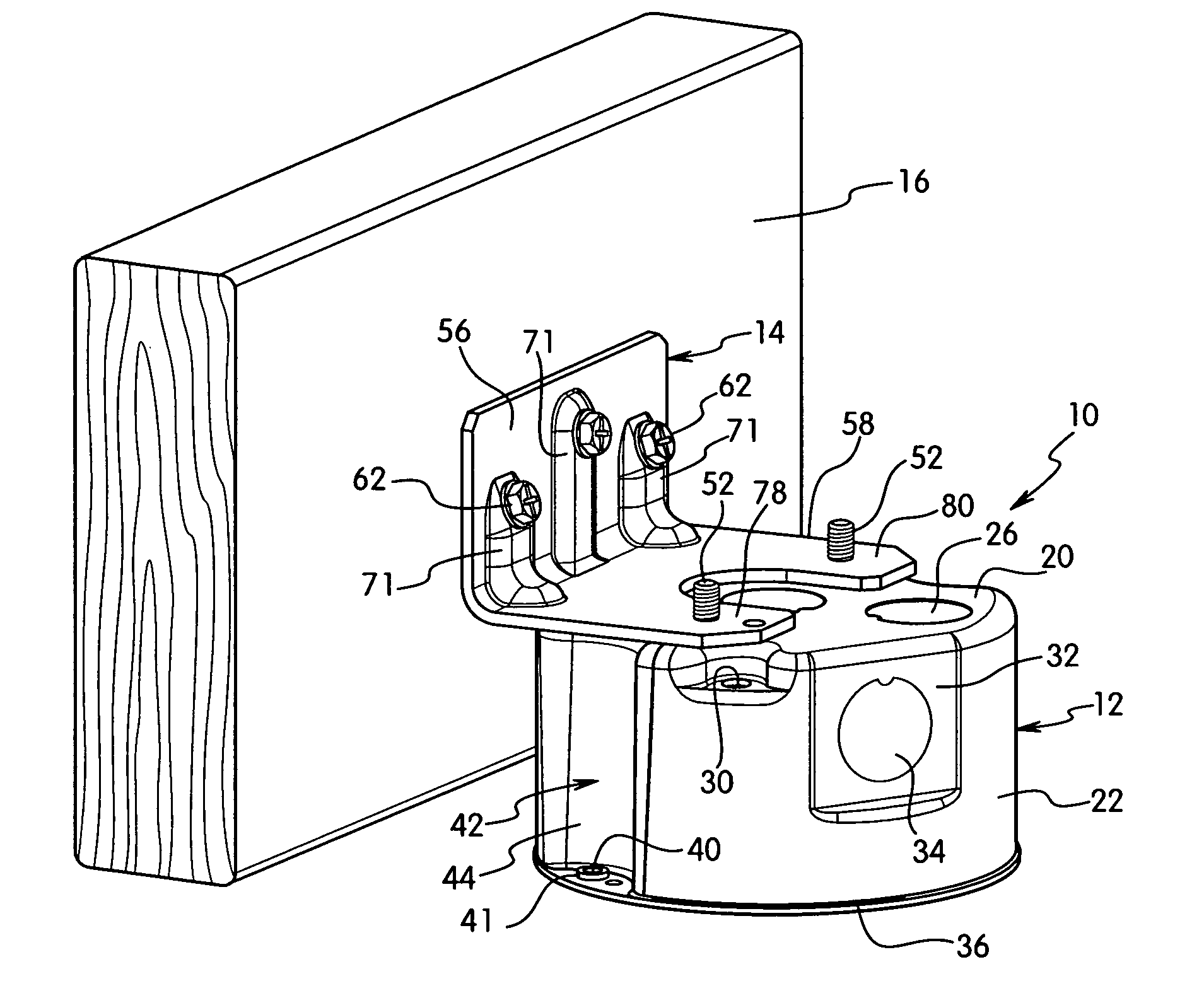
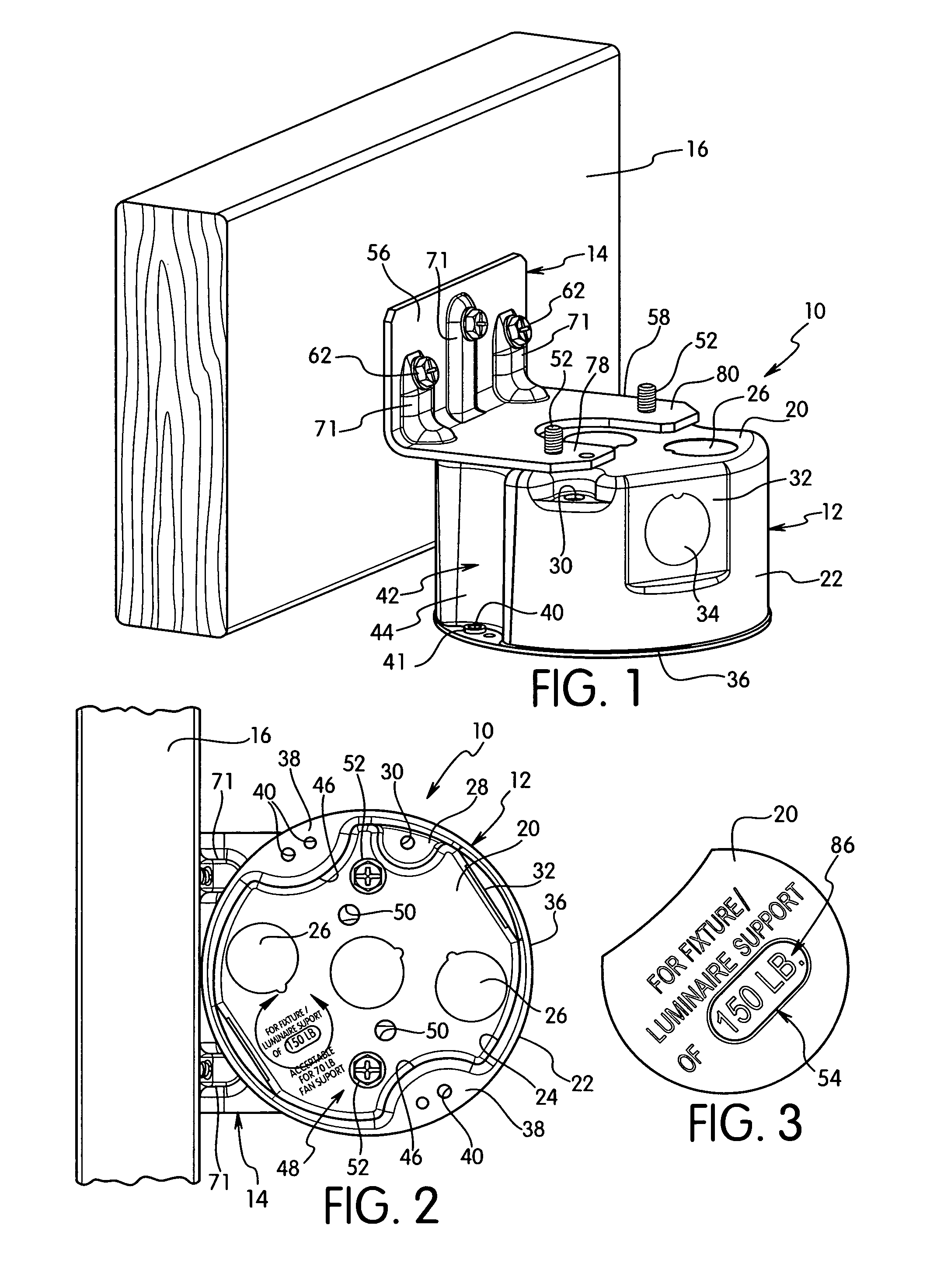
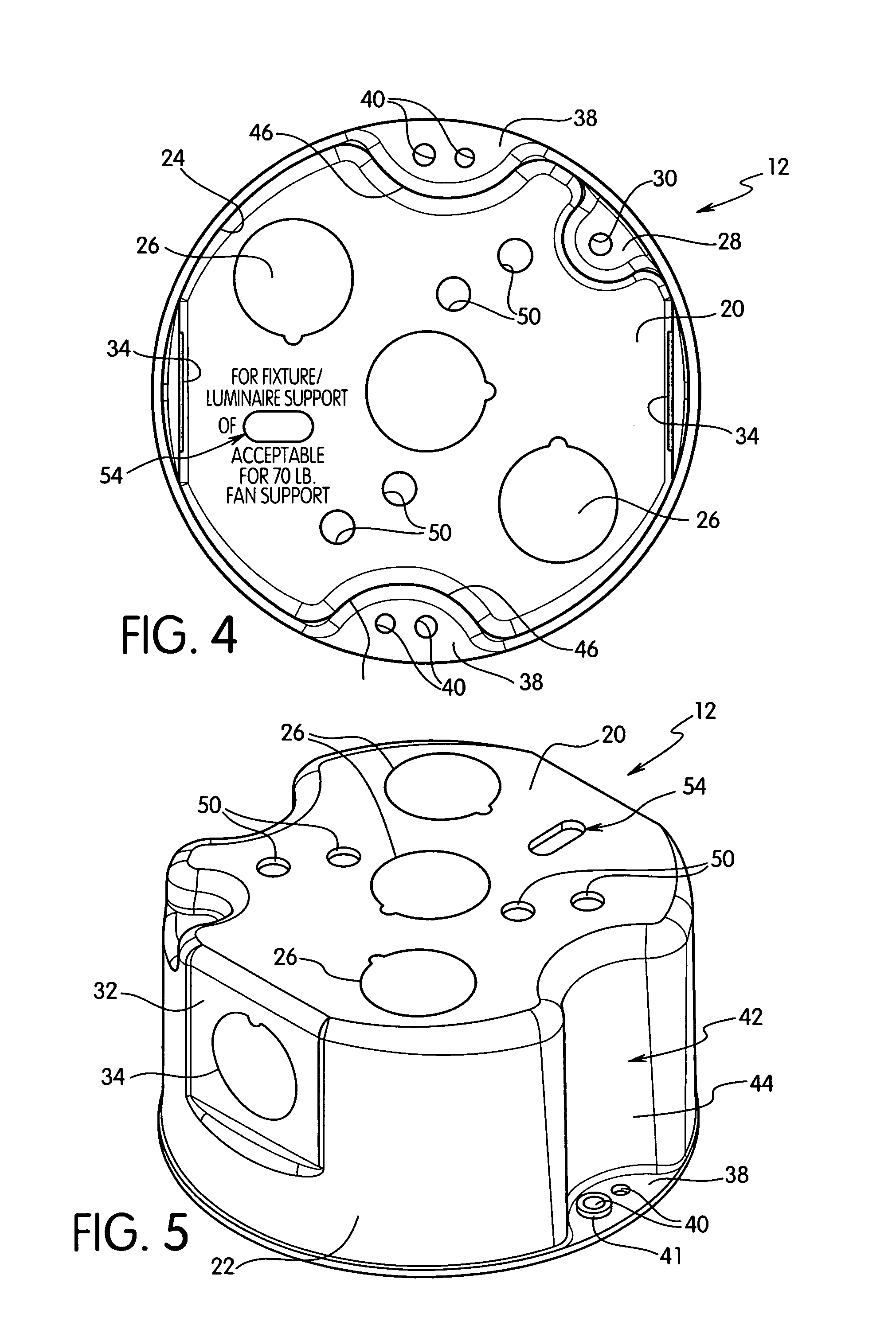
The present invention is an electrical box assembly that includes a mounting bracket and an electrical box. The mounting bracket has a label or other identifying markings that can be visually inspected after installation. The mounting bracket can be mounted in different orientations for supporting the electrical device in a desired position. The mounting bracket can have a load rating that is different from the load rating of the electrical box, allowing for flexibility in the orientation of the mounting bracket. The electrical box assembly is suitable for new construction and old work, and the mounting bracket can be adapted for different load ratings. The assembly includes a rear wall with a sight opening and a plurality of apertures for receiving a mounting fastener. The mounting bracket has printed indicia that is visible through the sight opening when the electrical box is coupled to the arm. The invention provides an improved electrical box assembly that allows for easy visual inspection of the mounting bracket and flexibility in the orientation of the mounting bracket.

Problems solved by technology

In particular, the load rating is often difficult to view or is obscured by the electrical box after installation of the box on the bracket.
However, these devices do not allow inspection of a mounting bracket after installation.

Method used


Image

  • Electrical box having sight window and mounting assembly
  • Electrical box having sight window and mounting assembly
  • Electrical box having sight window and mounting assembly

Examples


Embodiment Construction

[0038]The invention is directed to an electrical box assembly 10 having an electrical box 12 and a mounting bracket 14. The invention is particularly directed to an electrical box assembly where the mounting bracket has a label or indicia identifying a predetermined property where the label or indicia is visible through an opening in the electrical box after installation of the electrical box to assist with ease of inspection of the label or indicia after installation of the electrical box. The invention is further directed to an electrical box assembly that enables verification of a load rating of a mounting bracket after installation of the electrical box to the mounting bracket and / or support structure.

[0039]The electrical box assembly 10 is adapted for mounting to a support structure in various orientations depending on the electrical box and the construction of the support structure. The electrical box assembly is suitable for use in new construction and old work or existing co...


PUM


Abstract

An electrical box and support assembly includes an electrical box and a mounting bracket. The mounting bracket has a support arm for coupling with the bottom side of the electrical box. The support arm has printed or embossed indicia identifying the load rating of the mounting bracket. The electrical box has a bottom wall with a sight window with a dimension to enable visual inspection of the indicia on the mounting bracket after installation of the electrical box to the mounting bracket.

Description

FIELD OF THE INVENTION[0001]The present invention is directed to an electrical box assembly for mounting to a support structure. The present invention is particularly directed to a mounting bracket that can be mounted in a selected orientation and where the electrical box can be mounted to the mounting bracket with indicia on the mounting bracket being visible through an opening in the electrical box.BACKGROUND OF THE INVENTION[0002]Electrical boxes are typically mounted to a support structure either by directly attaching the box to the support or to a bracket that is attached to the support structure. Electrical devices, such a ceiling fan or light fixture, require an electrical box that has a suitable load rating for supporting the weight of the electrical device. Mounting brackets, the electrical box and electrical device assembly are required to have specific load bearing ratings for subsequent inspection after the electrical box is installed.[0003]Electrical inspectors and buil...

Claims


Application Information

Patent Timeline
Patent Type & Authority Patents(United States)
IPC IPC(8): H02G3/10
CPCH02G3/10
Inventor KORCZ, KRZYSZTOF W.JOHNSON, STEVEN J.
Owner HUBBELL INC
Learn More