Air seed meter

a technology air filter, which is applied in the field of air seed meter improvement, can solve the problems of requiring compensation, increasing the likelihood, and creating a “chimney effect” or “chimney effect” in the discharge chute, so as to reduce the effect of “chimney effect” and increase the cross sectional area

Inactive Publication Date: 2005-09-22
KINZE MFG INC
View PDF1 Cites 82 Cited by
  • Summary
  • Abstract
  • Description
  • Claims
  • Application Information

AI Technical Summary

Benefits of technology

[0017] Moreover, generally radial slots are provided between adjacent sealing segments of the inside edge of the vacuum cover. These slots separate the grooved sealing segments and extend generally radially of the central opening of the vacuum cover, but they are slightly inclined relative to a radius. Specifically, the slots extend outwardly and slightly incline in the direction of rotation of the disc when proceeding from an inner location to an outer location. Further, the slots are enlarged in cross sectional area proceeding from inner to outer locations. Thus, the slots are less likely to become clogged with fines; and the fines are delivered in a direction facilitating their being entrained in the air flow into the vacuum chamber from which they are evacuated. This permits the innermost central opening of each clearing slot to clear the central open area of the disc by permitting fines to be drawn into the vacuum chamber and evacuated. It also prevents the fines from getting caught between contacting adjacent surfaces of the disc and vacuum cover.
[0018] It will thus be appreciated that the combination of spaced, grooved sealing segments on the inner contact edge of the vacuum cover, together with the inclined, radial slots separating the sealing segments do not form a complete seal between the cover and the disc. Rather, what is formed is what is referred to as an “air dam” or controlled air barrier between the external atmosphere and the interior of the vacuum chamber, permitting a continuous, controlled flow of air from the atmosphere into the interior of the vacuum chamber for purging the contact region between the disc and inner edge of the vacuum cover of debris and clearing the central, exposed portion of the disc adjacent the disc / vacuum cover contact. This arrangement also aids in controlling undesired leakage of air, and it extends the useful life of the disc.
[0019] Another area in which the present invention improves on prior designs of air seed meter is in establishing a more uniform pressure differential between the two surfaces of the seed disc by establishing a uniformity of atmospheric pressure throughout the seed reservoir. This is accomplished by designing air inflow to the seed reservoir to compensate to air lost to the vacuum. In one aspect, a slotted insert is provided to overlay a large aperture on the back wall of the seed housing. The slots are sized such that they contain the seeds in the reservoir, but they are extended in length to permit air to flow inwardly over an extended region. Secondly, an opening is formed in the side wall of the seed housing adjacent the entrance of the discharge chute to reduce any “chimney” effect described above. In addition, if desired, the disc may be provided with additional apertures located in the central portion of the disc, which is located in the central opening of the vacuum cover when the disc and vacuum cover are assembled. In combination, these features permit make-up atmospheric air to flow into the reservoir over a distributed area to equalize atmospheric pressure within the seed reservoir over a wide range of operating conditions.
[0020] Another area of improvement in the present invention is in the singulation of seeds. This is accomplished by locating the seed cells extending to the periphery of the disc so the seeds do not have to move axially of the disc when released to clear the cell, and by providing, for each seed cell, a seed aperture or orifice extending through the disc for communicating the vacuum source with the reservoir for securing the seed. In addition, adjacent each seed orifice (in the corn disc) communicates with a pair of seed recesses in the reservoir side of the disc including a circumferential recess extending in the direction of rotation, and a radial recess extending radially inward toward the center of the disc. The circumferential recess facilitates seating of a seed and guidance of the seed into communication with the seed orifice and then securing the seed once seated and singulated. The radial recess extends from the seed orifice toward the center of the disc and it promotes removal of duplicate seeds, in combination with the singulator mechanism.
[0021] The singulator mechanism of the present invention comprises a series of three brushes extending radially inwardly of the disc and inclined slightly in the direction of rotation of the disc when proceeding inwardly of the periphery of the disc. Each brush comprises two sets of bristles and tends to dislodge a duplicate seed if it is present and competing for a seat. It has been found that the inclusion of three separate, spaced brushes enhances the accuracy of the meter by rejecting duplicates, usually at the first two brush stations, yet permitting each orifice to be filled with a seed.
[0022] The brushes of the singulator are mounted in a single body which is adjustable radially of the seed disc by means of a lever accessible, externally of the meter. The brushes are arranged for progressively more aggressive singulating action. The adjustment lever is easily accessible and quickly, conveniently and accurately manipulated. The outer edge of the seed disc is beveled so that the singulating brushes may extend more easily inwardly of the disc to engage and dislodge duplicate seeds from the seed cells, and to facilitate radial movement of the seeds as they are released.

Problems solved by technology

There are some difficulties associated with such arrangements.
Still further problems existed in that a “chimney effect” may be created in the discharge chutes of some existing meters.
This also increases the likelihood that air is drawn up the discharge chute (i.e. if the reservoir is at a pressure even slightly below atmospheric), resulting in a “chimney effect” or updraft of air in the discharge chute and requiring compensation.
The chimney effect not only reduces the reliability of accurate seed release, and therefore spacing, but depending upon the velocity of air flowing in a reverse direction in the seed discharge chute, it might alter the discharge flight path of the seed, thereby further affecting the fall time (and ultimate spacing) of seeds.
This effect creates variation in the length of seed travel (and thus variations in delivery time) from release to deposit, and thus results in inconsistency in seed spacing in the furrow.
Another difficulty with such prior art air meters as described above, is that for the most part, the seal between the disc and the vacuum housing is generally a circular path centered on the axis of rotation of the disc and located at the perimeter of the disc.
In such structures, the portion of the disc engaging the circular seal tends to create a narrow annular region of engagement between the seal member and the disc or seal, thus creating a narrow band of wear on the disc.
This wear “ring” creating wear on the disc or seal, results in a variance between the surface of the disc which was attempted to be sealed and the contact surface of the seal, thus reducing the effectiveness of some seals.
Moreover, such prior art structures rendered it difficult to clear the interior of the vacuum chamber as well as the exterior from fine particles, dust, dirt and chips or broken segments of seeds that may have cracked (collectively referred to as “debris” or “fines”).
Such particles could pass through or obstruct the apertures in a seed recess and may even accumulate between contacting surfaces where it was difficult, due to the nature of some prior devices, to clear the debris.
However, the cross section of such slots tended to reduce, with diminished clearing effect, as the sealing member wore into the surface of the disc, thereby reducing the dimensions in and effectiveness of the clearing passageways.

Method used


Image

  • Air seed meter
  • Air seed meter
  • Air seed meter

Examples


Embodiment Construction

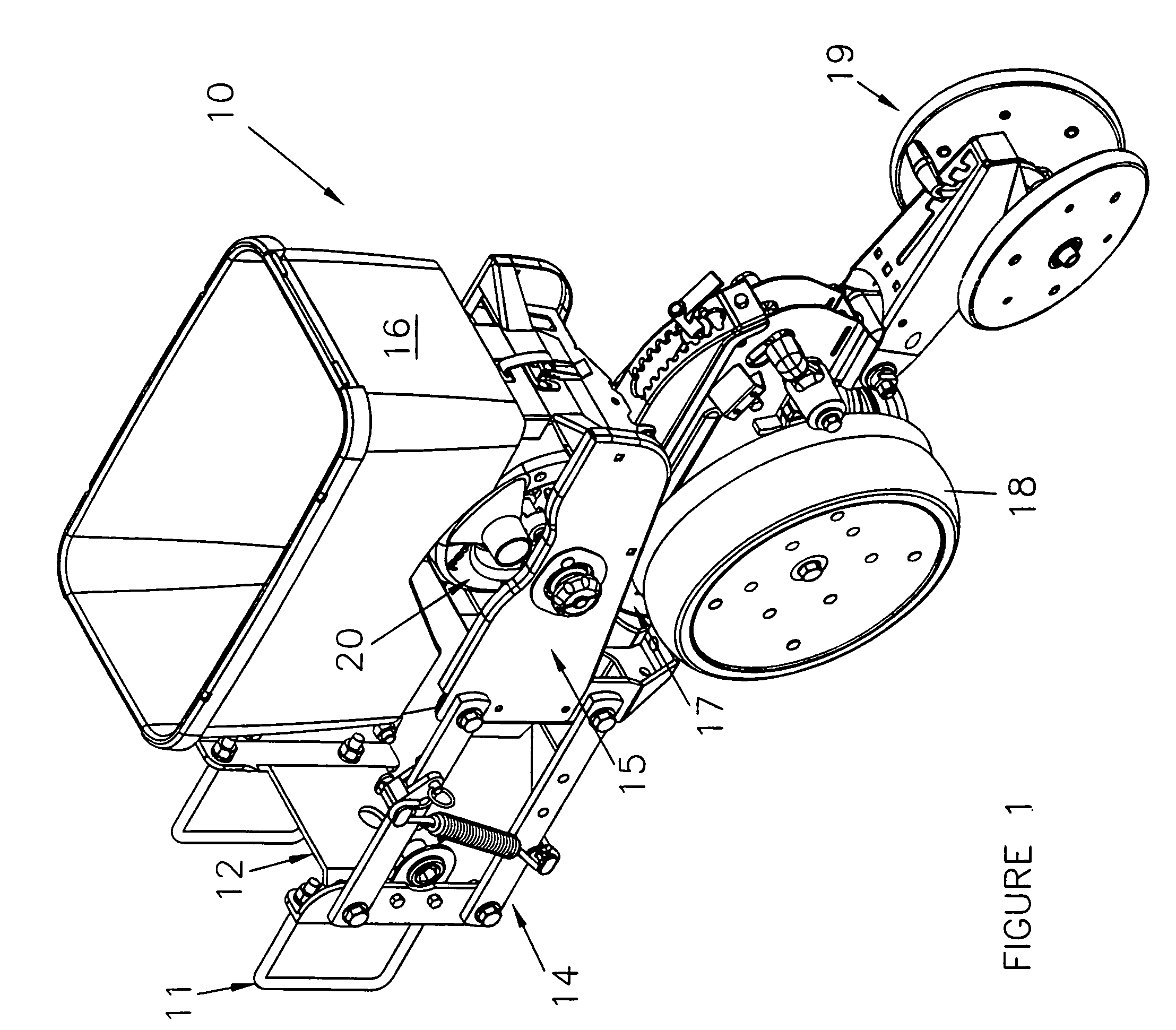
[0050] Referring first to FIG. 1, reference numeral 10 generally designates a planter row unit incorporating the air seed meter of the present invention. Briefly, the row unit 10, aside from of the inventive air seed meter is known in its general aspects to persons skilled in the art. The row unit includes a U-bolt mount generally designated 11 for mounting the row unit to a conventional planter frame or tool bar, as it is sometimes called, which may be a steel tube of 5 by 7 inches (although other sizes are used, as well).

[0051] The mount 11 includes a faceplate generally designated 12 which is used to mount left and right side parallel linkages, each linkage being a four-bar linkage such as the left one seen in FIG. 1 and generally identified by reference numeral 14. The double linkage is sometimes described as having upper parallel links and lower parallel links, and the rear ends of all four parallel links are pivotally mounted to the frame of the row unit generally designated ...


PUM


Abstract

An air seed meter for an agricultural planter includes a vacuum cover which has a central opening which exposes the central portion of the seed disc to the exterior. The central opening of the vacuum cover is centered on a location offset from the axis of rotation of the seed disc. This reduces disc wear at the disc-vacuum cover interface, and renders the disc more accessible for self-cleaning, visual inspection and verification of the proper disc. Openings in the central, open portion of the disc, the back wall of the seed housing and the side wall of the seed housing cooperate to equalize the air pressure in the seed reservoir to atmospheric pressure and reduce or eliminate reverse air currents in the discharge chute. An adjustable brush with three separate stations cooperates with an edge-release, beveled disc to apply a progressively more forceful singulation force to eliminate duplicate seeds.

Description

RELATED APPLICATIONS [0001] This application claims the benefit of U.S. Provisional Application No. 60 / 553,349 filed on Dec. 29, 2003 for “AIR SEED METER”.FIELD OF THE INVENTION [0002] The present invention relates to improvements in air seed meters of the type used to meter and “singulate” seeds in row units for agricultural planters. Air seed meters which use atomospheric pressure on the seed reservoir side of a rotating disc and a pressure below atmospheric pressure on the “vacuum” side (the pressure differential maintaining seeds on a rotating disc from a seed reservoir to a discharge location), are frequently referred to as “vacuum” meters, to distinguish them from seed meters which use a differential pressure generated by atmospheric pressure and a pressure greater than atmospheric pressure to retain the seeds on the disc (“positive pressure” meters). [0003] The principles of the present invention relate to air seed meters in general, whether the pressure differential securing...

Claims


Application Information

Patent Timeline
Patent Type & Authority Applications(United States)
IPC IPC(8): A01C7/00A01C7/04A01C9/00
CPCA01C7/046
Inventor EBEN, MARK H.DUNHAM, LISLE J.BARRY, ALAN F.
Owner KINZE MFG INC
Why Eureka
Try Eureka