Flexible tubular pipe for hydrocarbon transport with carcass consisting of an elongated element stapled with a band iron

a tubular pipe and hydrocarbon technology, applied in the direction of flexible pipes, pipes, mechanical equipment, etc., can solve the problems of limited thickness, affecting the ability of pipes to be used, and each pipe diameter poses a limitation on the possible depth at which pipes can be used, so as to increase the inertia of the carcass, reduce the cost of the carcass, and increase the capacity of withstanding great depths

Inactive Publication Date: 2005-06-14
TECH FRANCE SA
View PDF18 Cites 41 Cited by
  • Summary
  • Abstract
  • Description
  • Claims
  • Application Information

AI Technical Summary

Benefits of technology

[0015]The combination of an elongate element and a strip allows a thinner strip to be used in order to obtain an inertia similar to that obtained with the interlocked S-shaped strip; thus, for a given pipe diameter, it is possible to produce a winding having a much higher inertia with an elongate element of large cross section combined with a thin strip, since according to the invention the inertia is no longer limited by the strip thickness associated with the winding diameter. Thus, by combining the strip with an elongate element, it is possible, for a given pipe diameter, to considerably increase the inertia of the carcass that can be produced compared with the known carcasses. Thus, for each pipe diameter, its capability of withstanding great depths is increased.
[0016]Since the cost of stainless steel wire is less than the cost of stainless steel strip, combining the elongate element with the thin strip makes it possible to lower the cost of the carcass relative to a stainless steel strip carcass of the prior art. In addition, instead of stainless steel wire, it is possible to use other corrosion-resistant materials such as a sheathed steel wire, the manufacturing cost of which is even more attractive, thus further reducing the cost of the carcass. The coating on the wire may be of any type especially a thermoplastic coating, such as a polyethylene, polyamide or polyvinylidene floride (PVDF). It may also be made of a thermoset, such as an epoxy or the like.
[0017]It is also possible to use non-metallic yarns, such as those made of a composite (resin / carbon or glass fiber). Such yarns have the advantage of being lighter and thus lightening the structure, this being important especially in the case of pipes designed for great depth.
[0018]In the combination of the elements of the invention, the elongate element serves, on the one hand, to partly provide the inertia of the section by providing its material and, on the other hand, to guarantee the height of the section. It allows the strip to bear on itself so as to guarantee the shape and profile of the strip, thus allowing said strip to fully contribute to increasing the inertia of the section. The strip provides the interlocking, in order to keep the inter-turn gap between a minimum value and a maximum value, thus guaranteeing locally a minimum inertia of the carcass, and it also provides a large contribution to the inertia of the carcass. In addition, it substantially reduces the head loss problems associated with the gaps.
[0019]The use of a thin strip allows it to be bent to much smaller radii of curvature than with the strips used in the prior carcasses. Thus, since the thin strip has much smaller bending radii, the head losses associated with the gaps that would exist at the internal face of the carcass, especially because of the large radii of curvature of the adjacent strip turns, are, thanks to the invention, reduced.

Problems solved by technology

This thickness is limited, in particular because of the S-section, which it is impossible to wind over a given diameter for strip thicknesses greater than the limiting thickness.
Consequently, for a given pipe diameter, the carcass that can be used poses a limitation on its collapse resistance (inertia) characteristics.
Since the design of a carcass depends directly on the hydrostatic pressure that exists at the depth at which the pipe is used, the latter being designed to be able to withstand the hydrostatic pressure that there would likely be in the annulus in the pipe if the sheath were punctured, each pipe diameter poses a limitation on the possible depth at which the pipe can be used, this limitation being tied to the strength of its carcass.
Moreover, such carcasses produced from interlocked S-sections also have other problems, these being in particular:an inertia problem associated with a mean fill factor;a cost problem associated with the cost of the raw material employed (generally stainless steel in order to be corrosion-resistant); anda head loss problem due to the gaps, which may be substantial, between adjacent turns of the winding and which create discontinuities in the surface of the internal face of the carcass.
These problems are greater when it is desired to have a high inertia and when a thick strip is used.
However, the latter solution proves to be expensive and poses other problems, in particular a weight problem when the pipe is used at great depth.
There are also in the prior art carcasses made from spiralled wire, but these are in no way suitable for the type of applications envisioned here, especially on account of their inability to provide a local minimum inertia and therefore inability to ensure that the carcass has the desired resistance to collapsing.
Thus, the known carcasses of the prior art are unsatisfactory when it is desired to produce pipes intended to be used at great depth.
They have problems either of cost and weight (profiled wire) or of a limitation in the diameter of the pipe that can be used for a given depth (interlocked S-shaped strip), as well as head loss problems.

Method used


Image

  • Flexible tubular pipe for hydrocarbon transport with carcass consisting of an elongated element stapled with a band iron
  • Flexible tubular pipe for hydrocarbon transport with carcass consisting of an elongated element stapled with a band iron
  • Flexible tubular pipe for hydrocarbon transport with carcass consisting of an elongated element stapled with a band iron

Examples


Embodiment Construction

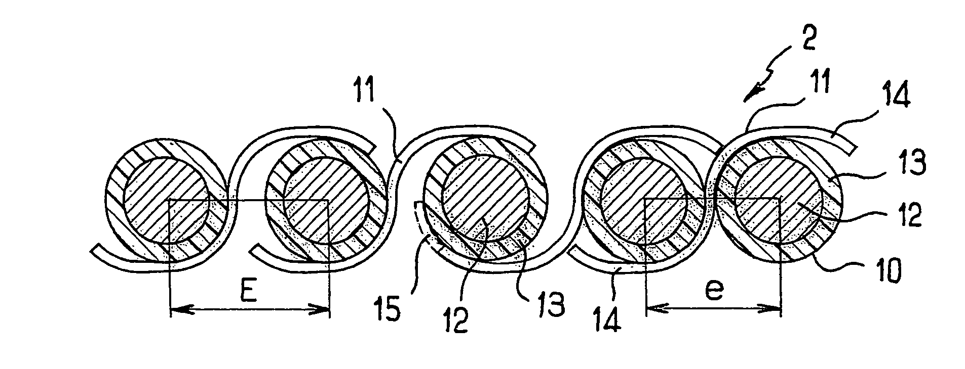
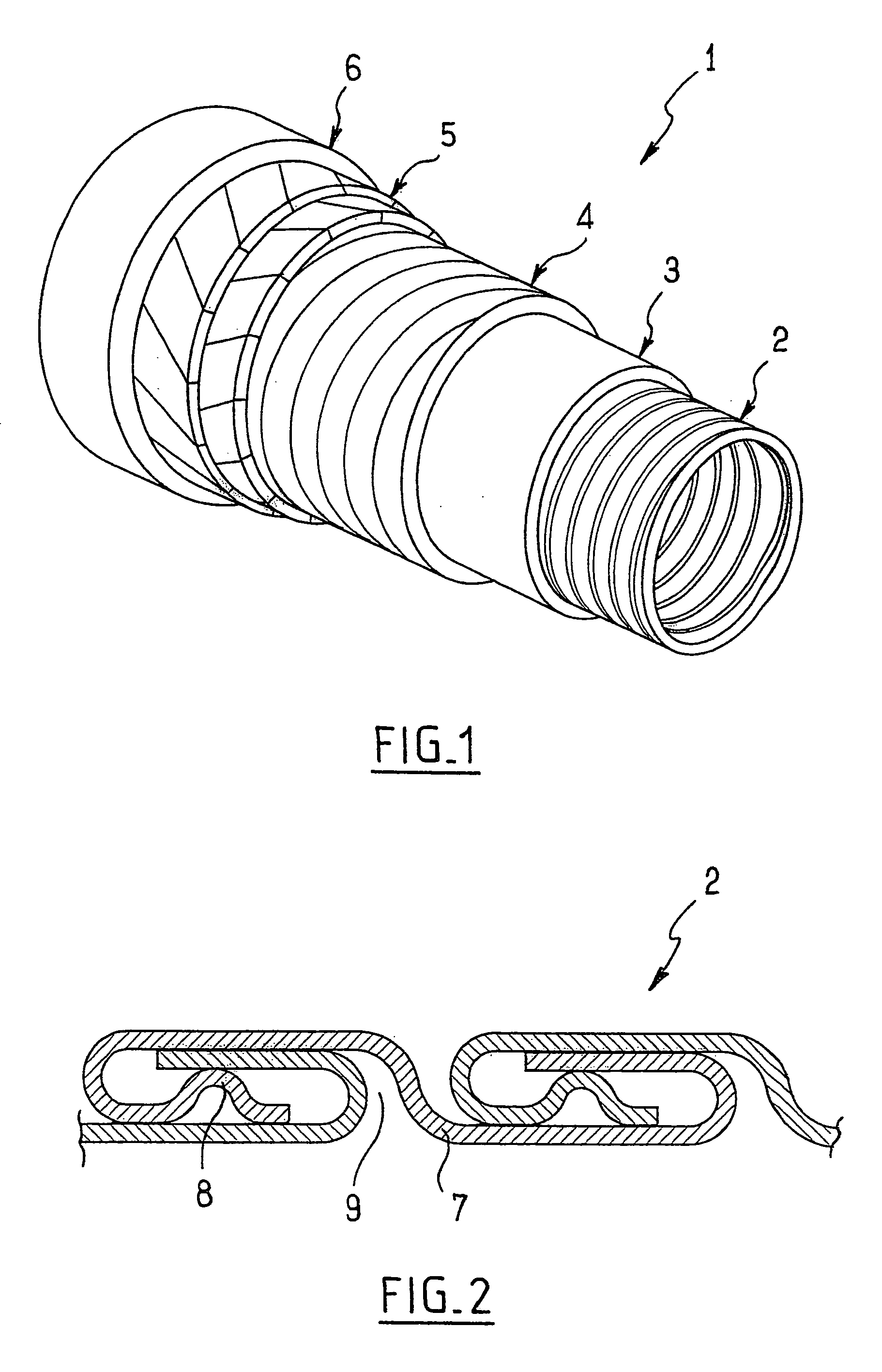
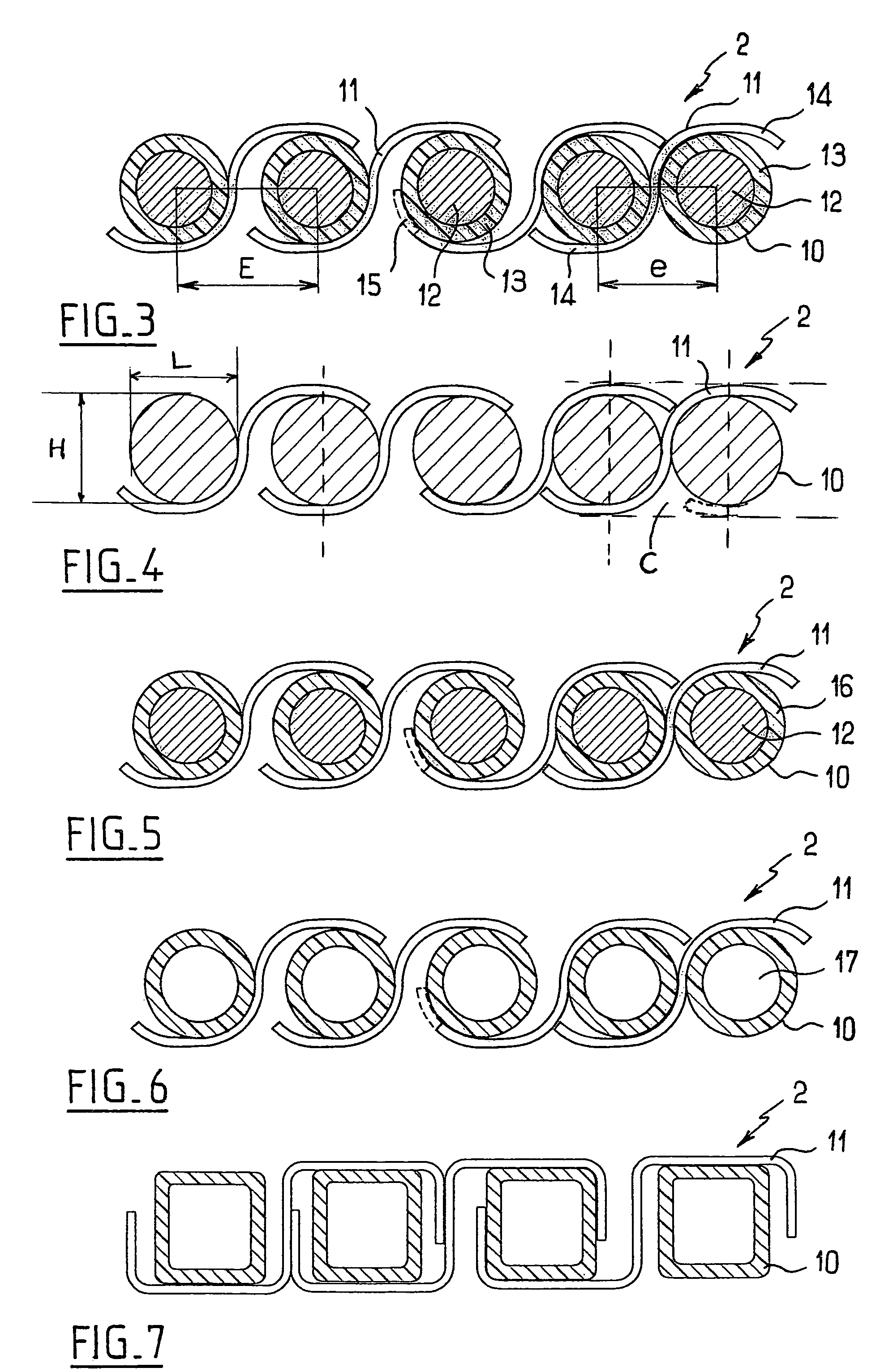
[0035]The flexible pipe 1 shown in FIG. 1 comprises, from the inside outward:[0036]a carcass 2 consisting of an interlocked metal winding so as to prevent the pipe from collapsing under the external pressure;[0037]an inner sealing sheath 3, made of a plastic, generally a polymer, resistant to the chemical action of the fluid to be transported;[0038]a pressure vault 4 mainly resistant to the pressure developed by the fluid in the sealing sheath and consisting of a short-pitch helical winding (that is to say one with a winding angle close to 90°) around the inner sheath of one or more interlocked (self-interlockable or otherwise) profiled metal wires. The profiled wires have a cross section in the form of a Z or T, or derivatives (teta or zeta) thereof, or in the form of a U or in the form of a I;[0039]at least one tensile armour ply 5 (and generally at least two crossed plies) wound with a long pitch; the lay angle measured along the longitudinal axis of the pipe is, for example, app...


PUM


Abstract

A flexible tubular pipe for hydrocarbon transport, comprising from inside to outside at least a carcass, an inner sheath, tensile armoring plies and an outer sheath, wherein the carcass is formed by winding of at least an anti-corrosive elongated metal element with large cross-section, with successive windings stapled with a thin anti-corrosive metal strip.

Description

BACKGROUND OF THE INVENTION[0001]The present invention relates to a flexible tubular pipe for transporting hydrocarbons, of the type comprising at least one carcass, an inner sealing sheath, tensile armour plies and an outer sealing sheath. Such a pipe, commonly called a “rough bore” when the carcass constitutes the inner layer of the pipe, can in particular be used for transporting hydrocarbons in offshore oil production installations. It may optionally include, in addition to these layers, other special layers, such as a pressure vault, a hoop layer, intermediate sheaths, etc.[0002]The carcass is, as will be recalled in the API 17J recommendations by the American Petroleum Institute, a tubular layer, in principle the inner layer, formed from an interlocked metal winding intended essentially to prevent the collapse of the inner sealing sheath or of the pipe in the absence of internal pressure in the pipe, owing to the effect of the external pressure, the pressure generated by the t...

Claims


Application Information

Patent Timeline
Patent Type & Authority Patents(United States)
IPC IPC(8): F16L11/16F16L11/00
CPCF16L11/16F16L11/083
Inventor JUNG, PATRICE JOEL LOUISDUPOIRON, FRAN.CEDILLA.OIS
Owner TECH FRANCE SA
Why Eureka
Try Eureka