Computing method for unsteady flow field of rotary impeller machinery based on three-dimensional dynamic mesh

A technology of unsteady flow field and rotating impeller, applied in calculation, special data processing applications, instruments, etc., can solve the problem of sudden increase in complexity, unsuitable dynamic mesh technology for three-dimensional unsteady flow field calculation and calculation errors of rotating impeller machinery Termination and other issues to achieve the effect of fast iteration speed

Inactive Publication Date: 2013-07-31
SOUTH CHINA UNIV OF TECH
View PDF3 Cites 16 Cited by
  • Summary
  • Abstract
  • Description
  • Claims
  • Application Information

AI Technical Summary

Problems solved by technology

However, when the dynamic mesh method is applied to the three-dimensional situation, the complexity increases sharply, and the deformed mesh often has a negative volume, which leads to the termination of the calculation error. Therefore, the application of the dynamic mesh technology is still limited to two-dimensional or quasi-three-dimensional (two-dimensional domain stretched in the normal direction) in the case of
[0004] In view of the slow iteration speed of the sliding mesh method, the existing dynamic mesh technology is not suitable for the calculation of the three-dimensional unsteady flow field of the rotating turbomachinery, so it is necessary to improve the calculation method of the unsteady flow field of the rotating turbomachinery

Method used


Image

  • Computing method for unsteady flow field of rotary impeller machinery based on three-dimensional dynamic mesh
  • Computing method for unsteady flow field of rotary impeller machinery based on three-dimensional dynamic mesh
  • Computing method for unsteady flow field of rotary impeller machinery based on three-dimensional dynamic mesh

Examples


Embodiment

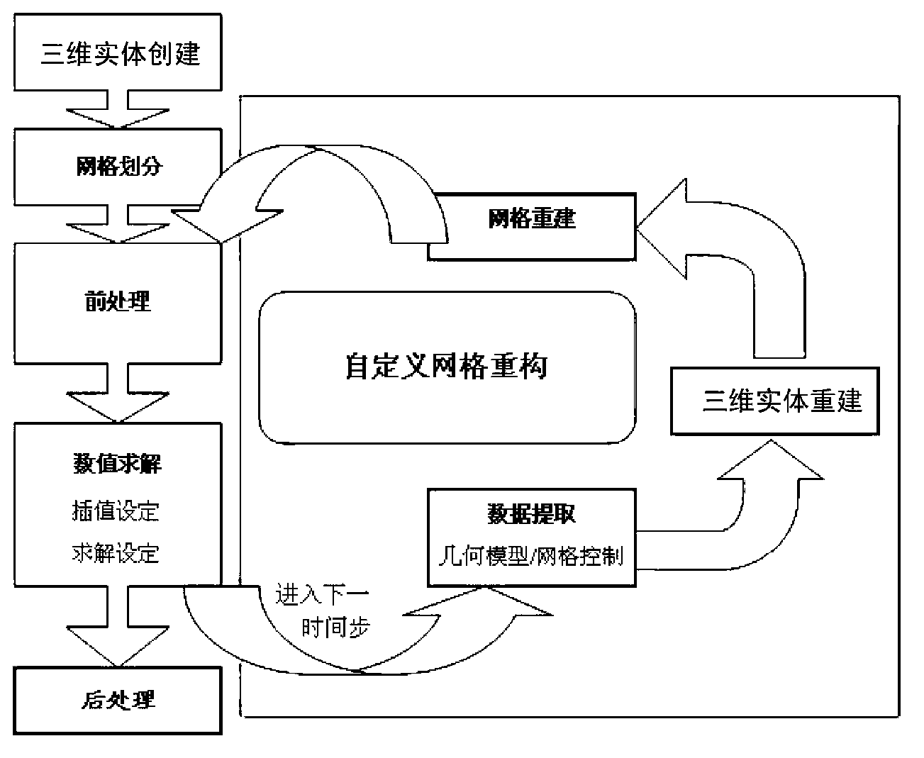
[0036] The calculation method of the unsteady flow field of the present invention is applied to a rotary impeller machine, which refers to a machine that is pressurized by the centrifugal force generated by the rotation of the impeller, such as a centrifugal pump, a centrifugal compressor, a mixed flow pump, an axial flow pump, a shaft flow compressor, centrifugal fan, axial flow fan, etc.; the flow chart of the inventive method is shown in figure 1 , including the following steps:

[0037] The first step is to define the rotating working area with the impeller and the area directly connected with the rotating working area in the rotary turbomachinery as the calculation domain, and use mechanical drawing software (such as Pro / E software) to construct the three-dimensional entity of the calculation domain to form a three-dimensional Physical documents;

[0038] The second step is to use meshing software (such as ICEM software) to read the 3D solid file, mesh the computational ...


PUM


Abstract

The invention provides a computing method for an unsteady flow field of rotary impeller machinery based on a three-dimensional dynamic mesh. The method is applied to the technical field of rotary impeller machinery, is based on the technology of three-dimensional dynamic mesh, realizes the compute of the unsteady flow field of rotary impeller machinery, and has higher iteration speed compared with the traditional sliding mesh method.

Description

technical field [0001] The present invention relates to the technical field of rotary impeller machinery, and more specifically, relates to a calculation method for an unsteady flow field of a rotary impeller machinery. Background technique [0002] At present, the conventional unsteady flow calculation methods of rotating impeller machinery mainly include slip grid method. In the reference system (non-inertial system), the sliding grid rotates with the reference system without regeneration, and the quality of the initial grid can be maintained, and the rest of the calculation domain is set in the inertial system. The slip interface is used for data docking between the two reference systems, so as to realize the calculation of the overall flow field. However, the sliding grid method uses data docking between multiple reference systems, which affects the continuity in time, so the iteration speed of the sliding grid method is slow. [0003] A common method to solve unsteady...

Claims


Application Information

Patent Timeline
Patent Type & Authority Applications(China)
IPC IPC(8): G06F17/50
Inventor 黄思陈志胜
Owner SOUTH CHINA UNIV OF TECH
Why Eureka
Try Eureka