
Redundant drive active overconstrained three-degree-of-freedom parallel machine tool

An over-constraint, degree of freedom technology, applied to milling machines, milling machine equipment, milling machine equipment details, etc., can solve problems such as nonlinearity, strong coupling, large work space, and weak coupling, and achieve simple topology and large work space , the effect of weak coupling

Inactive Publication Date: 2018-01-05
BEIJING JIAOTONG UNIV
View PDF0 Cites 12 Cited by
  • Summary
  • Abstract
  • Description
  • Claims
  • Application Information

AI Technical Summary

Problems solved by technology

[0003] In recent years, the most successful example of the application of parallel mechanisms with few degrees of freedom to parallel machine tools is the application of Tricept series and Exechon series manipulators and their modules on parallel / hybrid machine tools. The mechanism configurations are 3UPS-UP and 2UPR-SPR, respectively. Although it has been widely used in the industrial field, it has nonlinearity, strong coupling, and complex control. In order to overcome the above shortcomings, a kind of redundant drive active with one movement and two rotations has been synthesized through configuration evolution and topology change. The over-constrained three-degree-of-freedom parallel mechanism, as a special parallel mechanism with few degrees of freedom, has the advantages of weak coupling, large working space, high flexibility, low inertia, high stiffness, high precision, and good structural symmetry. It has become a research hotspot and the focus of domestic and foreign research

Method used


Image

  • Redundant drive active overconstrained three-degree-of-freedom parallel machine tool
  • Redundant drive active overconstrained three-degree-of-freedom parallel machine tool
  • Redundant drive active overconstrained three-degree-of-freedom parallel machine tool

Examples


Embodiment 1

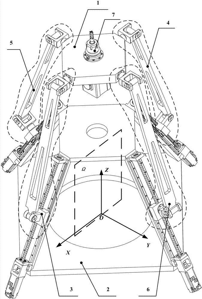
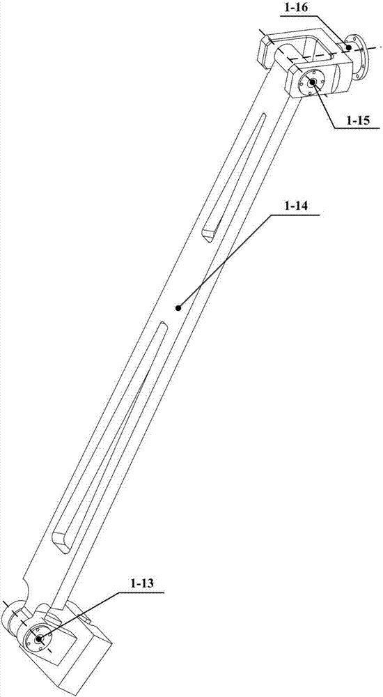
[0038] Such as figure 1 The schematic diagram of the overall structure of the redundantly driven active over-constrained three-degree-of-freedom parallel machine tool is shown, which includes the moving platform 1, the fixed platform 2, the first kinematic branch group 3, the second kinematic branch group 4, and the third kinematic branch group 5. The fourth movement branch chain group 6. The spindle head 7. Wherein the structure of the first motion branch chain group and the second motion branch chain group is exactly the same, and it is the main drive PRU branch, which includes a servo drive unit, a rotating subassembly, a branch chain body and a Hooke hinge, and the servo drive unit (such as figure 2 Shown) consists of servo motor 1-1, motor support 1-2, coupling 1-3, bearing 1-7, bearing support 1-4 (1-8), bearing end cover 1-9, ball wire Bar 1-6, nut pair 1-5, guide rail 1-10, slide block 1-11, the servo motor 1-1 is fixed on the motor support 1-2, and the motor support...

Embodiment 2

[0042] Such as Figure 5 The schematic diagram of the overall structure of the redundant drive active over-constrained three-degree-of-freedom parallel machine tool is shown in Fig. Chain group, third motion branch chain group, fourth motion branch chain group, spindle head. Among them, the first motion branch group and the second motion branch group have the same structure, are the main drive PRU branch, and their structure and composition are the same as those in Embodiment 1.

[0043] The difference from Embodiment 1 is that the third motion branch group and the fourth motion branch group are the main drive PUU (II) type branches, as shown in Figure 6, the first rotary shaft 2 of the Hooke hinge -1 is perpendicular to its second rotation axis 2-2, the first rotation axis 2-1 is in the same direction as the guide path of the servo drive unit, and the second rotation axis 2-2 is perpendicular to the first rotation axis 2-4 of another Hooke hinge Parallel, its second rotatio...

Embodiment 3

[0045] Such as Figure 7 As shown, the schematic diagram of the overall structure of the redundant drive active over-constrained three-degree-of-freedom parallel machine tool. The second movement branch chain group, the third movement branch chain group, the fourth movement branch chain group, and the spindle head. Wherein the first motion branch chain group and the second motion branch chain group have the same structure, are the main drive PRU branches, and their structure and composition are the same as those in Embodiment 1.

[0046] The difference from Embodiment 1 is that the third motion branch chain group is the main drive PUU (I) type branch, the first rotary axis of the Hooke hinge is perpendicular to its second rotary axis, and the second rotary axis is parallel to the coordinate axis Parallel, and the second rotation axis is parallel to the first rotation axis of another Hooke hinge, its second rotation axis is perpendicular to the first rotation axis, and the ext...


PUM


Abstract

The invention relates to a kind of redundantly driven active over-constraint three-degree-of-freedom parallel machine tool, which includes a moving platform 1, a fixed platform 2, and a first kinematic branch group 3, a second kinematic branch group 4, and a moving platform connected to the fixed platform. The third movement branch group 5, the fourth movement branch group 6, the structure of the first movement branch group and the second movement branch group are exactly the same, and the servo drive unit connects the branch body and the Hooke hinge through the rotating pair Connected with the moving platform, the third motion branch chain group is connected to the branch chain body through the Hooke hinge by the servo motor unit and connected to the moving platform through the Hooke hinge, and the fourth motion branch chain group is connected to the branch chain body by the servo drive unit through the Hooke hinge And the Hooke hinge or compound spherical hinge is connected with the moving platform. The invention synthesizes a three-degree-of-freedom parallel machine tool with two rotations and one movement, which has the advantages of simple branch chain, symmetrical structure, high degree of recombination and modularization, strong load capacity, excellent comprehensive performance, large working space, and avoidance of singular configurations, etc. It has good engineering practical application prospects.

Description

technical field [0001] The invention belongs to the technical field of machining and manufacturing of parallel machine tools, and specifically relates to a type of over-constrained parallel machine tool configuration based on 2PRU and 2RPU as the main drive, and is especially suitable for high-precision machining of complex special-shaped curved surfaces. Background technique [0002] At present, the traditional three-coordinate machine tool has the advantages of large working space and high flexibility, but because of the serial structure, the machine tool is large in size, long in the transmission chain, poor in stiffness, and has error accumulation; the traditional five-coordinate machine tool is based on the three-coordinate machine tool A 2-3 degree of freedom rotary head is installed at the end of the moving platform or a 2 degree of freedom rotary table is added, but its structure is open chain, and the mass of the moving parts is large, resulting in large motion inert...

Claims


Application Information

Patent Timeline
IPC IPC(8): B23C1/00B23C9/00
Inventor 张海强房海蓉方跃法杨会姜丙山
Owner BEIJING JIAOTONG UNIV
Learn More