Hybrid direct-current current-limiting breaker

A hybrid DC and circuit breaker technology, applied in the direction of emergency protection circuit devices, electrical components, etc., can solve the problems that it is difficult to meet the requirements of the DC system to quickly break the fault current, the current cannot be turned off, and the on-state loss is large, and it is easy to realize , Protection system security, high reliability effect

Active Publication Date: 2017-10-20
INST OF ELECTRICAL ENG CHINESE ACAD OF SCI
View PDF3 Cites 16 Cited by
  • Summary
  • Abstract
  • Description
  • Claims
  • Application Information

AI Technical Summary

Problems solved by technology

The difference from the AC system is that the current of the DC system does not have a natural zero-crossing point, so the natural zero-crossing point of the current cannot be used in the DC system to shut down like the AC system, so the breaking of the DC fault current has always been a problem worth studying. subject
The on-state loss of traditional mechanical DC circuit breakers is low, but affected by the time required for oscillation and the breaking speed of conventional mechanical switches, it is difficult to meet the requirements of DC systems for quickly breaking fault currents; solid-state DC circuit breakers need to use more devices in series, making them Large on-state loss and high cost

Method used


Image

  • Hybrid direct-current current-limiting breaker
  • Hybrid direct-current current-limiting breaker

Examples


Embodiment Construction

[0017] The present invention will be further described below in conjunction with accompanying drawing and specific embodiment:

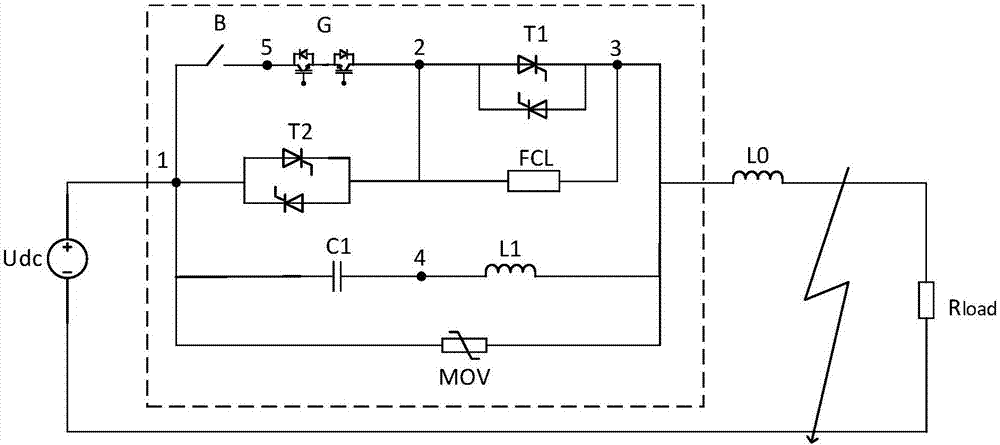
[0018] figure 1 Shown is a specific embodiment 1 of the present invention. The hybrid DC current limiting circuit breaker of embodiment 1 includes a fast mechanical switch B, an IGBT module G, a thyristor module T2, a thyristor module T1, a current limiter FCL, an inductor L1, a capacitor C1 and Lightning arrester MOV.

[0019] The fast mechanical switch B is connected between the connection point 1 and the connection point 5, the IGBT module G is connected between the connection point 2 and the connection point 5, the fast mechanical switch B and the IGBT module G are connected in series, and the thyristor module T2 is connected at the connection point Between point 1 and connection point 2, thyristor module T1 and current limiter FCL are connected between connection point 2 and connection point 3, thyristor module T1 and current limiter FCL are co...


PUM


Abstract

A hybrid direct-current current-limiting breaker comprises a rapid mechanical switch B, an IGBT module G, a thyristor module T1, a thyristor module T2, a current limiter FCL, an inductor L1, a capacitor C1 and a lightning arrester MOV. The rapid mechanical switch B is connected between a connecting point 1 and a connecting point 5, the IGBT module G is connected between a connecting point 2 and the connecting point 5, the rapid mechanical switch B is connected with the IGBT module G in series, the thyristor module T2 is connected between the connecting point 1 and the connecting point 2, both the thyristor module T1 and the current limiter FCL are connected between the connecting point 2 and a connecting point 3, and the thyristor module T1 is connected with the current limiter FCL in parallel; and the capacitor C1 is connected between the connecting point 1 and a connecting point 4, the inductor L1 is connected between the connecting point 3 and a connecting point 4, the capacitor and the inductor are connected in series, and the lightning arrester MOV is connected between the connecting point 1 and the connecting point 3. During stable operation of a power grid, the breaker presents low impedance, and influence on the power grid is small; and when a fault occurs in a direct current transmission line, fault current limiting and cutoff of the faulty line can be rapidly realized.

Description

technical field [0001] The invention relates to a hybrid DC current-limiting circuit breaker topology, in particular to a high-voltage DC current-limiting circuit breaker topology for a flexible DC grid. Background technique [0002] DC circuit breaker is one of the key equipment to ensure the stable, safe and reliable operation of DC power transmission and distribution system and DC grid system. The difference from the AC system is that the current of the DC system does not have a natural zero-crossing point, so the natural zero-crossing point of the current cannot be used in the DC system to shut down like the AC system, so the breaking of the DC fault current has always been a problem worth studying. subject. [0003] In order to quickly and effectively isolate DC faults, ensure the safe and stable operation of DC grid-related equipment, and minimize the impact of faults on the operation of AC and DC systems, it is necessary to use high-voltage DC circuit breaker technol...

Claims


Application Information

Patent Timeline
Patent Type & Authority Applications(China)
IPC IPC(8): H02H7/26
CPCH02H7/268
Inventor 肖立业滕尚甫张志丰邱清泉韦统振张国民
Owner INST OF ELECTRICAL ENG CHINESE ACAD OF SCI
Why Eureka
Try Eureka