Video signal encoding device and video signal encoding method

a video signal and encoding technology, applied in the field of video signal encoding device and video signal encoding method, can solve the problems of increasing the volume of computation required to calculate increasing power consumption, complicated computation of the coefficient of a filter characteristic, etc., and achieves the effect of increasing the load on the computation section and increasing the power consumption

Inactive Publication Date: 2006-09-21
MITSUBISHI ELECTRIC CORP
View PDF10 Cites 41 Cited by
  • Summary
  • Abstract
  • Description
  • Claims
  • Application Information

AI Technical Summary

Benefits of technology

[0003] As described in the foregoing, with such a conventional video encoding method, for making selections of the characteristics for the prefilter, an encoding difficulty is calculated from the encoding mode (s) used for encoding of images, the encode volume counted for every encoding mode, and the quantization step size counted also for every encoding mode. The resulting encoding difficulty is then used together with the encoding output rate to calculate , the coefficient of a filter characteristic. In such a manner, computation of the coefficient of a filter characteristic is complicated, and the volume of computation required to calculate the coefficient of a filter characteristic is thus increased.
[0004] This resultantly increases the load on a computation section configured by a CPU or others, thereby increasing the power consumption. The matter of this power consumption is considered specifically important when the power source such as battery allowed for installation is necessarily limited in number or size due to limited size of devices such as cellular phones.

Problems solved by technology

In such a manner, computation of the coefficient of a filter characteristic is complicated, and the volume of computation required to calculate the coefficient of a filter characteristic is thus increased.
This resultantly increases the load on a computation section configured by a CPU or others, thereby increasing the power consumption.
The matter of this power consumption is considered specifically important when the power source such as battery allowed for installation is necessarily limited in number or size due to limited size of devices such as cellular phones.

Method used


Image

  • Video signal encoding device and video signal encoding method
  • Video signal encoding device and video signal encoding method
  • Video signal encoding device and video signal encoding method

Examples


first embodiment

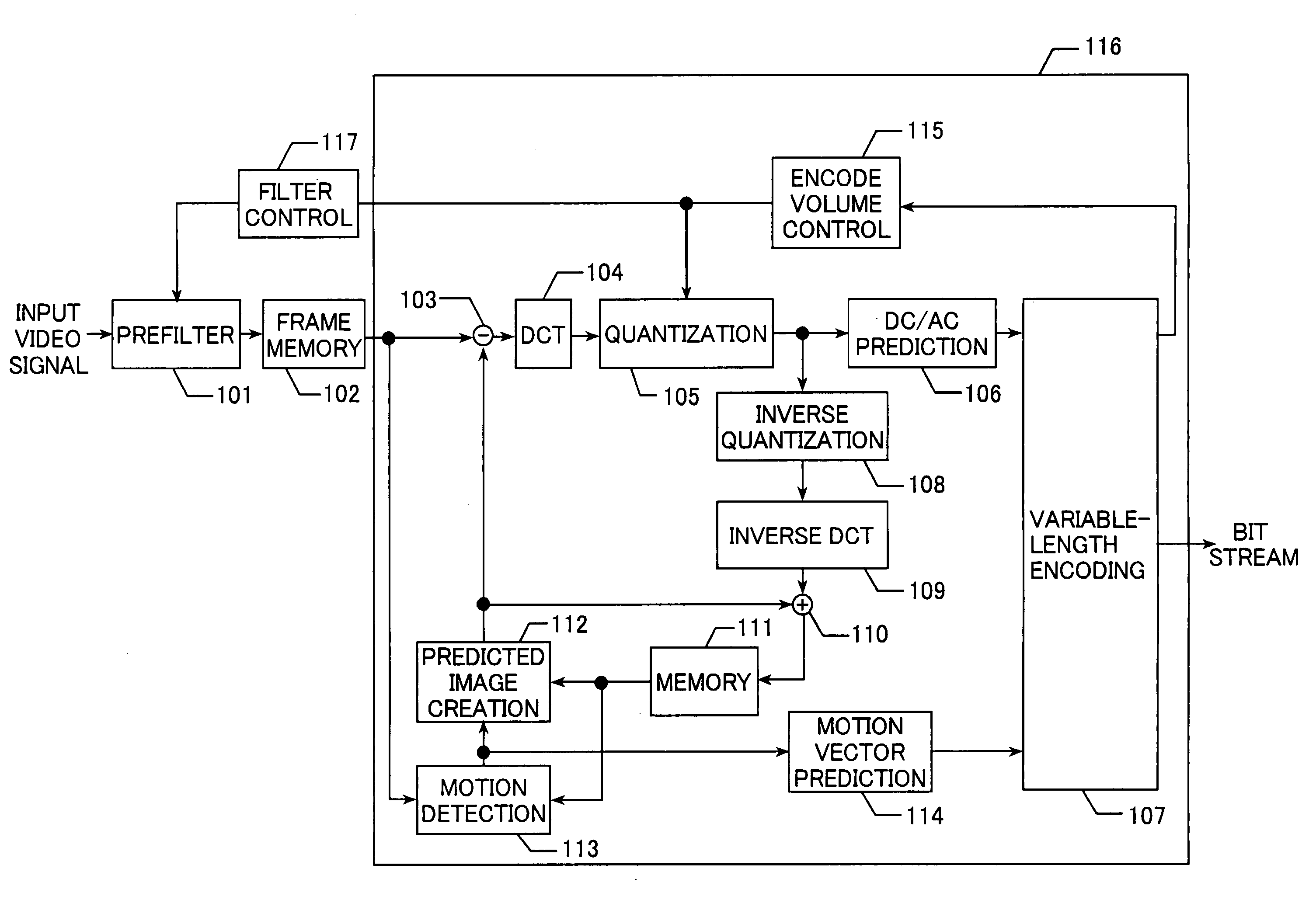
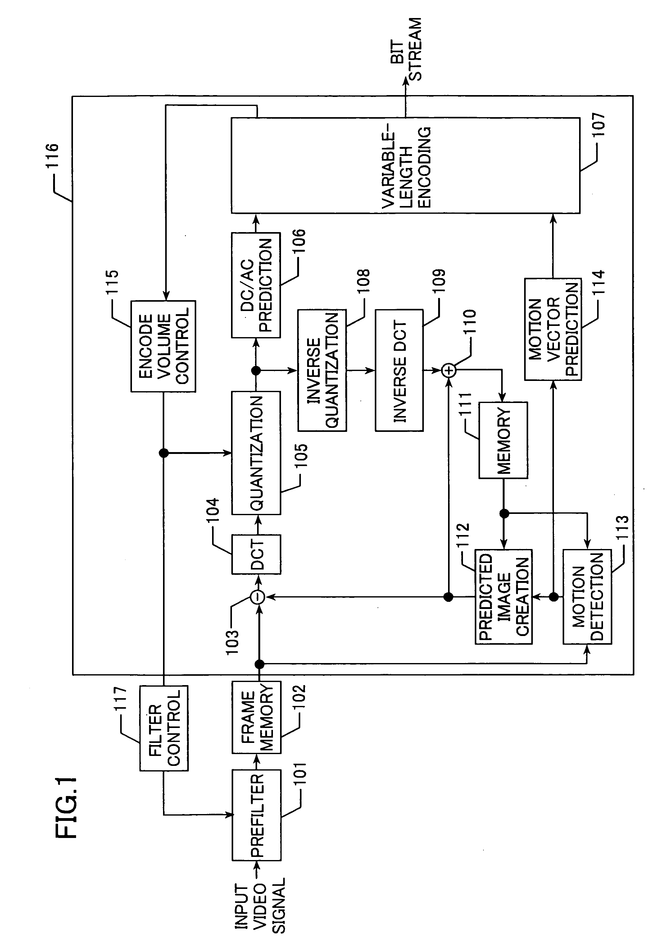
[0032]FIG. 1 is a block diagram showing a video signal encoding device in a first embodiment.

[0033] In FIG. 1, an incoming video signal is input into a prefilter 101 for extraction of any predetermined frequency components. Note that, in the below, the predetermined frequency components in the input video signal are referred also to as current image data.

[0034] The current image data thus extracted in the prefilter 101 is output to frame memory 102. Herein, the frame memory 102 is configured by storage means such as semiconductor memory, magnetic disk, optical disk, and others.

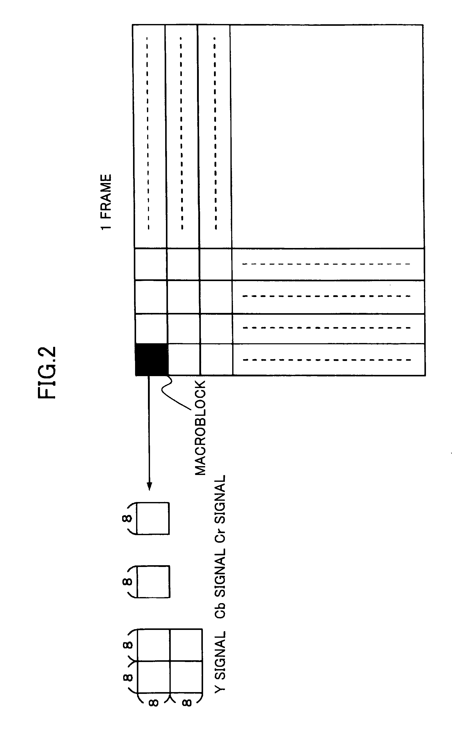
[0035] The current image data stored in the frame memory 102 is forwarded to encoding means 116 on a basis of macroblock shown in FIG. 2, and encoded by the encoding means 116. Herein, the encoding means 116 may perform encoding with any transformation method as long as the encoding method uses orthogonal transformation such as DCT, wavelet transformation, and Hadamard transformation for converting images i...

second embodiment

[0080] Generally, an incoming video signal includes noise components, and encoding such a noise-component-included input video signal will result in useless encode volume due to the noise components.

[0081] When the encode volume in the encoding means 116 is increased, the prefilter 101 in the first embodiment determines the filter characteristics control data K so as to eliminate high-frequency components. Therefore, when any useless encode volume is caused for the noise components, this resultantly eliminates the high-frequency components that are not supposed to be eliminated, thereby possibly causing degradation to displaying images.

[0082] In consideration thereof, a video signal encoding device in a second embodiment includes a noise reduction filter to the prefilter 101 so that the noise components are effectively controlled, and useless encode volume is prevented from causing in the encoding means 116.

[0083] Note here that the structure components of the second embodiment a...

third embodiment

[0099]FIG. 18 is a block diagram showing a video signal encoding device in a third embodiment.

[0100] In the third embodiment, the filter control means 117 and the encode volume control means 115 in the first or second embodiment are configured as one piece, and the resulting piece is referred to as encode volume control means 115a. Note here that the structure components other than the encode volume control means 115a and their operations are similar to those in the first or second embodiment.

[0101] Similarly to the first or second embodiment, the encode volume control means 115a outputs a quantiser scale Qp in the quantization means 105 based on the encode volume provided by the variable-length encoding means 107, and outputs to the prefilter 101 the filter characteristics control data K in accordance with the quantiser scale Qp.

[0102] As described in the foregoing, in the video signal encoding device in the third embodiment, the filter control means 117 and the encode volume co...


PUM


Abstract

Included are: a prefilter (101) for outputting, based on filter characteristics control data, predetermined frequency components in an input video signal as current image data; encoding means (116) for subjecting the current image data to an encoding process, and outputting encoding parameters together with a bit stream corresponding to current image data as a result of the encoding process; and filter control means (117) for outputting the filter characteristics control data that is set based only on one or two of the encoding parameters.

Description

TECHNICAL FIELD [0001] The present invention relates to devices and methods for encoding incoming video signals (hereinafter, referred also to as input video signals) and, more specifically, to a device and method suitable for cellular phones, TV phone systems, and the like. BACKGROUND ART [0002] In a conventional video encoding method, a prefilter having a plurality of characteristics is used to subject moving images to a filtering process prior to encoding, and the resulting moving images are encoded in one or more modes. The encoding mode (s) used for encoding the moving images are used to calculate an encoding difficulty together with the encode volume counted for every encoding mode, and the quantization step size counted also for every encoding mode. Using thus calculated encoding difficulty and any arbitrarily-set encoding output rate, the coefficient of a filter characteristic is calculated. Thus the calculated coefficient of a filter is used as a basis to make selections of...

Claims


Application Information

Patent Timeline
Patent Type & Authority Applications(United States)
IPC IPC(8): H04N11/04H04N7/12H04B1/66H04N11/02H04N7/26H04N7/50
CPCH04N19/172H04N19/61H04N19/85H04N19/124H04N19/152H04N19/117
Inventor FUKUTA, TOMONORIHATANO, YOSHIKO
Owner MITSUBISHI ELECTRIC CORP
Why Eureka
Try Eureka